

Hello to all,
Welcome to the new edition of the SOLIDWORKS® Support Monthly News! This monthly news blog is co-authored by members of the SOLIDWORKS® Technical Support teams worldwide. Here is the list of topics covered in this month’s Blog.
- How can I apply decal on part face excluding its background color in SOLIDWORKS® Visualize?
- Workaround to obtain the reaction moment on a fixed face having SOLID mesh.
- Overriding quantity using UNIT_OF_MEASURE custom property in PDM.
- How to ensure a SOLIDWORKS PDM system can reach the correct TCP port of a SQL instance?
How can I apply decal on part face excluding its background color in SOLIDWORKS® Visualize?
By Vinod KALE
Recently, there was a requirement where the user wanted to remove the background color of logo from the decal (refer the above image showing white color around text) in SOLIDWORKS® Visualize.
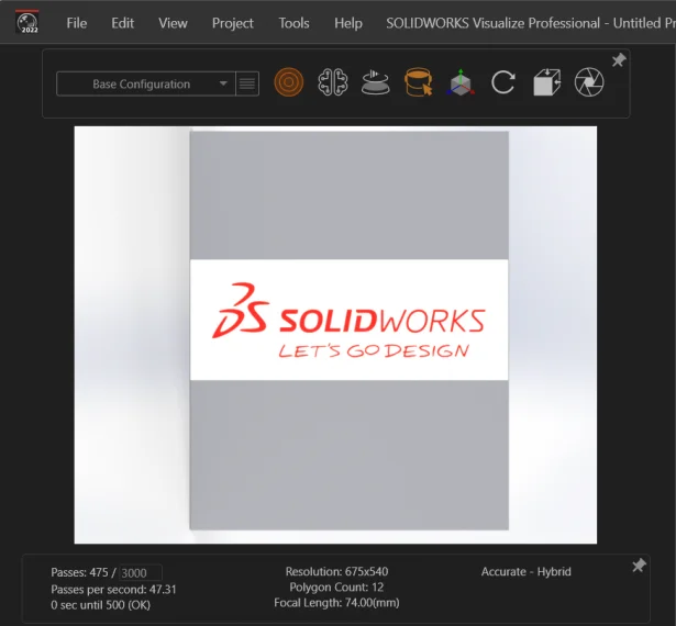
SOLIDWORKS® Visualize allows you to generate photo-quality images from the 3D CAD data. If you want to make any changes in the existing image that is not created from Visualize, you have to make use of Photo Editor applications (like Photoshop, Photopea, etc.) and then use that image in Visualize to get the desired output.
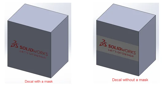
There are few ways you can insert decal without its background:
A. Create a decal with mask in SOLIDWORKS® > Insert decal on part face > Export the part to Visualize using its add-in.
Use following steps to create decal with mask:
- In the Task Pane in SOLIDWORKS®, select the Appearances, Scenes, and Decals tab
- Expand Decals and select the decals folder or a folder containing custom decals
- In the lower pane, identify the decal and drag it onto part face
- In the Decals PropertyManager, in the Image tab under ‘Mask Image’, Click Selective color mask
- Double-click the rectangular boxes to the right of Pick color
- In the Color dialog box, select the color, Click OK
- Items of the selected color are removed from the Decal Preview (but still some background color appear around alphabet)
- Open the decal image in MS Paint
- File > Save the image to ‘Monochrome Bitmap’ format
- Edit the inserted decal in SOLIDWORKS® > Select the ‘Image mask file’ under ‘Mask Image’ > Browse the mask file (Monochrome Bitmap) > Check ‘Invert mask’ option > Observe the background color around logo is now removed correctly.
B. The other way is to use ‘Online Photo Editor’ to remove background color from the decal image.
- a. Go to Photopea website and launch this online photo editor application
- Open the decal image.
- Create new layer and switch back to the Background layer.
- Click on the “Magic Wand” tool and select the logo related text from the image.
- Switch to ‘Layer 1’.
- Select the ‘Paint Bucket Tool’ and click on same alphabet. Observe some text gets added to new layer.
- Switch back to Background layer and repeat steps from ‘c’ to ‘e’ to add entire text.
- Once all alphabets are added to new layer, toggle the show/hide icon in Background layer to confirm that text displays correctly without its background color.
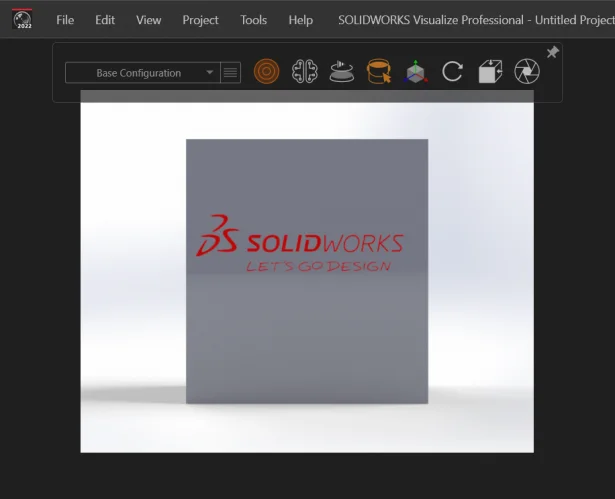
- File -> Export -> Save as PNG. Then use this image when inserting decal on part face in SOLIDWORKS® Visualize as shown in this image.
Workaround to obtain the reaction moment on a fixed face having SOLID mesh
By Suresh NIKALAJE
As we know, it is not possible to get the reaction moment on a fixed face of a solid mesh using the Reaction Force option. In SOLIDWORKS® Simulation, the nodes of solid elements have no degree of freedom in rotation (have only three translations degrees of freedom), therefore, the nodes on the face of a solid cannot have any nodal reaction moment. The Reaction Moment values are null if the selection is the face of a solid.
On the other hand, for the nodes on SHELLS (including sheet metal) and for nodes on BEAMS have 6 degrees of freedom per node (3 translations, 3 rotations). Therefore, you can plot, probe and list the Reaction moment on nodes that belong to shell and beam elements.
Even with this limitation of SOLID mesh, do you know the result force PropertyManager allows you to get the reaction moment on a fixed face using the ‘Free Body Force’ option?
If you want the reaction moment on a fixed face in you model, then follow this procedure:
- Create a ‘Point’ at the geometrical center of the face. [Go to Insert > Reference Geometry > Point & selects the Center of Face construction method in the PropertyManager]
- If the direction of the reaction moment you want are not aligned with global coordinate system, then create new with the orientation you desired.
- In the Simulation Manager tree, right click on the Results folder and select List Results Force
- Select ‘Free body force’ as the option. Select the ‘Point’ you created in the ‘Vertex of Reference Point for Location of Moment’ field, select the newly created coordinate system in the ‘Plane, Axis or Coordinate System’ fields and select the fixed face.
- The magnitude of moment components and resultant are listed in the Free body moment table.
For example, the expected reaction moment of a cantilever T beam of length L = 2000″ subjected to a force of 100 lbs acting on its free end is 2E+05 Ibf.in as see in following image.
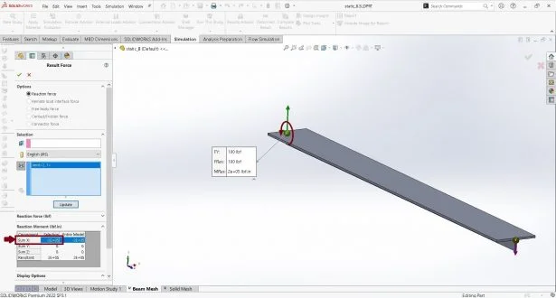
Fig 1: Reaction Moment using BEAM mesh
After creating new point at ‘Point’ at the geometrical center of the T face at fixed end, the Free body moment table shows expected reaction moment as 2 E+05 Ibf.in as shown below.
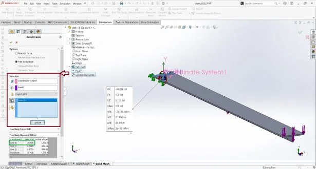
Fig 2: Reaction Moment using SOLID mesh
Note: To download the ‘Bending of a T Section Beam’ example model, browse to [drive letter:UsersPublicPublic DocumentsSOLIDWORKSSOLIDWORKS versionsamplesSimulation ExamplesVerificationStatic_8.SLDPRT].
Overriding quantity using UNIT_OF_MEASURE custom property in PDM
By James FALCONER
In SOLIDWORKS®, you can use the BOM Quantity override to display quantities instead of instance counts. A SOLIDWORKS® PDM computed BOM takes advantage of this feature when you map the part data card to the UNIT_OF_MEASURE property. The custom property UNIT_OF_MEASURE has a surprisingly powerful feature that not everyone may know about.
This feature is discussed in the SOLIDWORKS® PDM Admin Guide, but due to its brevity, could easily be missed:
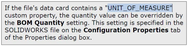
In SOLIDWORKS® PDM the quantity value is determined by the instance count of the file. But sometimes you may want to show an amount, such as length or quantity, instead of the instance count. The following steps will show us how PDM computed BOMs can provide a value by using a SOLIDWORKS® custom property. Let’s start by showing how BOM Quantity override works in SOLIDWORKS®.
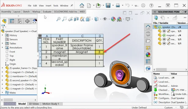
For this example we’ll use the basic speaker assembly that is included in most SOLIDWORKS® installations and found in the folder C:UsersPublicDocumentsSOLIDWORKSSOLIDWORKS 2022samplestutorialPDMWorks. Add and check these files into a PDM vault.
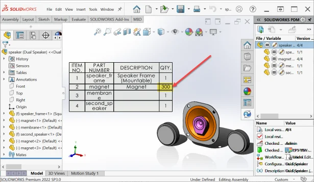
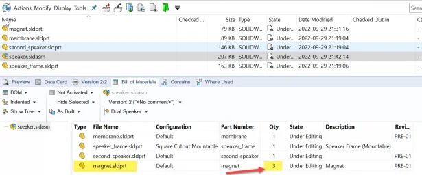
Open and check out speaker.sldasm main assembly and add 2 more instances of the magnet file by going to Insert > Component > Existing Part and select magnet.sldprt. Also, add an assembly BOM table. See the quantity value of 3 for magnet. This means there are 3 instances of Magnet in this assembly.
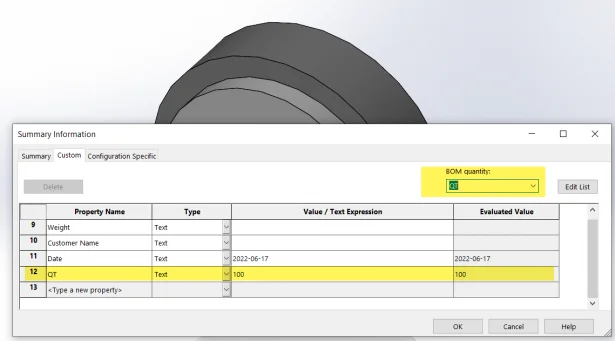
What if we wanted to override each instance with a different base quantity value? Close the assembly. Open and check out the magnet.sldprt file and create a Custom Property value named QT with a value of 100. Note BOM quantity override is by default set to – None -.
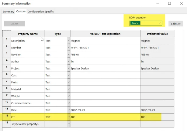
Select BOM quantity: QT as marked below & click OK. (Note BOM Quantity overrides the base quantity value). What this does is that the BOM quantity QT is overridden with the value of 100. These steps will be repeated for each file that needs to show a custom value for its quantity in a BOM. Save & check the file in.
Now, when we reopen the assembly we will see the overridden BOM quantity value of 300.
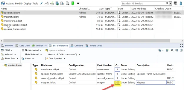
When this data set is stored in a default SOLIDWORKS® PDM vault, the default SOLIDWORKS® part card will automatically use the overridden BOM quantity value and display the 300 value.
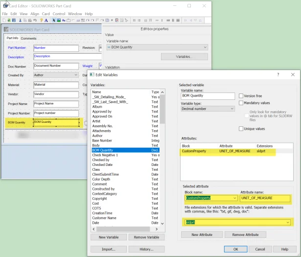
So how can we make use of this feature in other files, vaults, and data cards? In the PDM Admin Tool open the Card Editor and select the default SOLIDWORKS Part Data card: The CustomProperty UNIT_OF_MEASURE attribute will need to be used to override quantity value as described previously.
- Create a variable, named for example “BOM Quantity.
- Add a variable mapping with block “CustomProperty”, the attribute “UNIT_OF_MEASURE and the extension “SLDPRT”. Please note that this will be a read-only variable mapping and you cannot override this value via the data card.
- Add the variable to the SOLIDWORKS® part data card (.sldprt)
If we did not use the UNIT_OF_MEASURE override for the BOM Quantity variable, then we would have seen the regular instance count of magnet.sldprt as seen below (3).
How to ensure a SOLIDWORKS® PDM system can reach the correct TCP port of a SQL instance
By Tor IVEROTH
In order to communicate with the SQL server and access the file vault database, a SOLIDWORKS® PDM system establishes an ODBC connection over the TCP protocol to the SQL server instance name that is stored in the registry.
The SQL server instance listens on a specific TCP port. If the client system (or a server) cannot find the correct port to communicate over, log in to the vault will fail with various ODBC related communication errors.
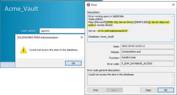
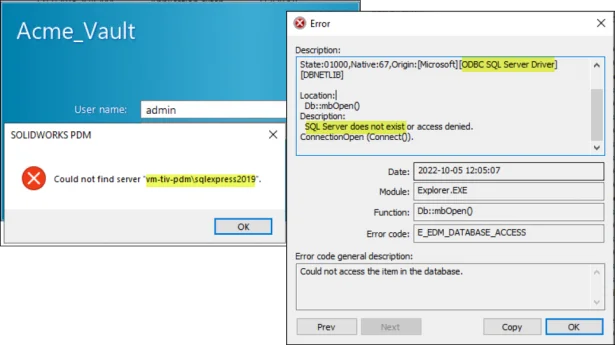
Some examples of errors that you would encounter if the system cannot reach the SQL server port are:
With SOLIDWORKS® PDM 2020 and later: The database access error would reference “ODBC Driver 17 for SQL Server”


With SOLIDWORKS® PDM 2019 and earlier : The database access error would reference “ODBC SQL Server Driver”.
Use the following troubleshooting guidelines to address this problem:
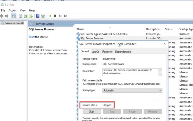
A – Start the SQL Server Browser service: The SQL Server Browser Service will broadcast the current SQL ports for each SQL instance on the Server. Make sure the service is started on the SQL server.
B – Confirm the SQL Server Instance name: The SQL server name will be in the form of a default instance name (SERVERNAME) or a named instance (SERVERNAMEINSTANCE).
When you create a vault view, or attach to an archive server, the SQL instance name will be stored in the registry. Make note of which SQL server name that the vault is using.
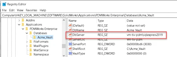
The connection details for the local file vault view of the vault:
“DbServer” value under key: HKEY_LOCAL_MACHINESOFTWARESolidWorksApplicationsPDMWorks EnterpriseDatabases[VAULTNAME]
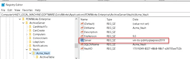
The connection details for the vault on the archive server:
“DbServer” value under key: HKEY_LOCAL_MACHINESOFTWARESolidWorksApplicationsPDMWorks EnterpriseArchiveServerVaults[VAULTNAME]
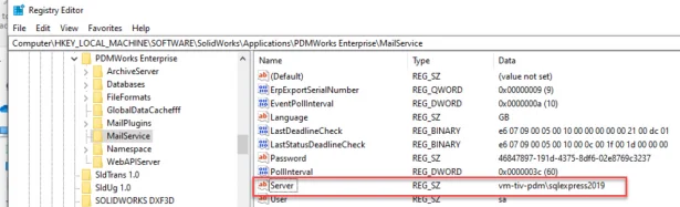
The connection details for the Database Server Service:
“Server” value under key: HKEY_LOCAL_MACHINESOFTWARESolidWorksApplicationsPDMWorks EnterpriseMailService
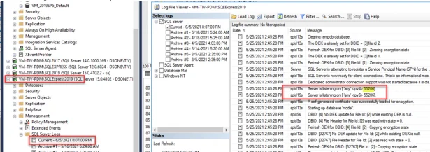
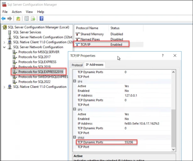
C – Verify the SQL instance TCP port: You can see what port the SQL server instance is currently listening on via the SQL log file (for more details, refer to Knowledge Base Solution S-051979).
In this example, the SQL Server named instance VM-TIV-PDMSQLEXPRESS2019 is listening on port 55206
Alternatively, you can find the current port via the SQL configuration manager, SQL Server Network Configuration, Protocols for SQLSERVERNAME, TCP, IP Addresses.
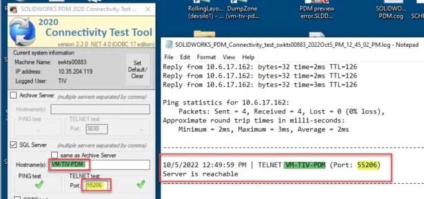
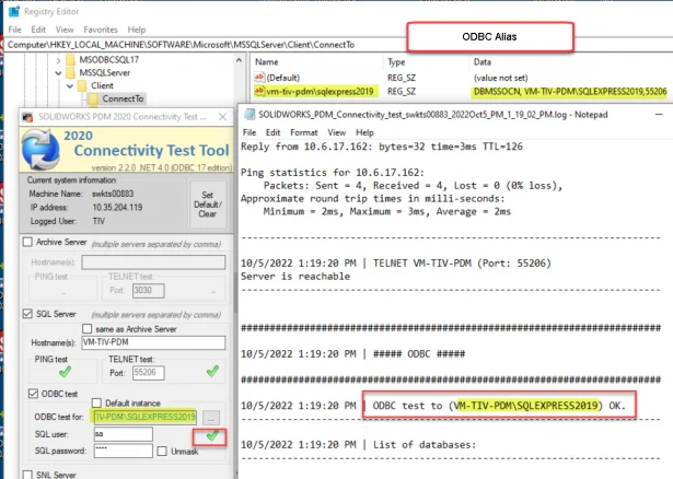
D – Make sure the system can reach the TCP port: Now that you know the correct SQL name and SQL port, the client system (or remote server) must be able to communicate over the specific TCP port that the SQL instance listens on. The easiest method to ensure the system can reach the SQL port is to use the SOLIDWORKS® PDM Connectivity Test Tool. You can find this tool in Knowledge Base Solution S-069274.
Run the tool and select the “SQL Server” option. Fill in the hostname of the SQL Server (note that if the SQL Server is a named instance (I.e. VM-TIV-PDMSQLEXPRESS2019), you should only fill in the server hostname (i.e. VM-TIV-PDM) in this field. Fill in the port to test (from step C).
If the port is accessible, the tool should show a success result.
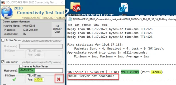
If the port is inaccessible, the test will fail. You should double check that you are connecting to the correct port (step C) and that the port is not blocked in the network (by firewall rule or similar). For example, this image shows that this system cannot connect to TCP port 42045.
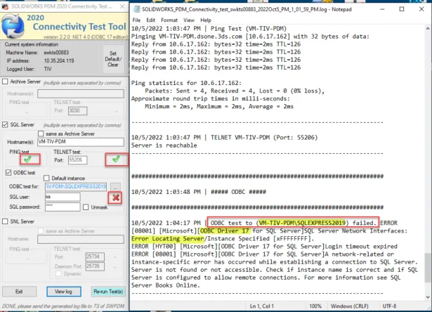
E – Create an ODBC connection alias: If the SQL TCP port is accessible, but the ODBC connection still fails, you should create an ODBC Alias in order for the system to use the correct port. An ODBC Alias maps the SQL instance name to a specified port number.
In this example, the SQL server host (VM-TIV-PDM) and the SQL instance port (55206) can be connected to, but the SQL instance name (VM-TIV-PDMSQLEXPRESS2019) cannot be resolved to the proper port. The connectivity test tool will have a similar error that the PDM client log shows.
To create the ODBC Alias:
- Read over the document in Knowledge Base Solution S-042701.
- Focus on the chapter “Creating an ODBC alias when using the using ODBC 17 (msodbcsql17.dll) driver”
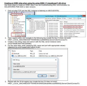
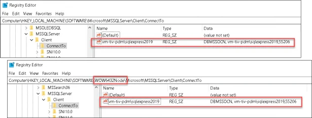
- Create the ODBC alias on the system that cannot establish an ODBC connection with the SQL server instance. Update with the SQL instance name (see step B) and the correct port (step C). For example, the ODBC Alias for an SQL instance named “VM-TIV-PDMSQLEXPRESS2019” to port “55206” should look like this under both the 64-bit and 32-bit registry (name should be: VM-TIV-PDMSQLEXPRESS2019 and the data value should have: DBMSSOCN, VM-TIV-
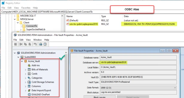
With the ODBC alias correctly defined, the connectivity test tool should now successfully connect to the SQL instance name, the port and successfully establish an ODBC connection.
The vault should now be accessible via the administration tool or local vault view.
If you are still unable to connect: Go over the chapter “After Installing SQL Server Express” in the install guide and make sure remote connections are allowed and that the TCP protocol is enabled.
Noteworthy Solutions from the SOLIDWORKS® Knowledge Base

When I use the SOLIDWORKS® PDM quick search or integrated search functionality, why do the SOLIDWORKS file open or save dialog boxes stop responding (hangs or crashes)?This problem can happen on a SOLIDWORKS® PDM client workstation if the file type associations for SOLIDWORKS files are incorrect. To get more information, see solution ID: S-079778

What can I do if every SOLIDWORKS® Flow Simulation project I run shows a ‘Preparing model’ Solver Monitor status indefinitely and any FloXpress analysis never finishes the ‘Meshing in progress’ step? To get more information, see solution ID: S-079776
Is there a SolidPractices document available on the topic of “SOLIDWORKS Toolbox”? The objective of this SolidPractices document is to share information that relates to setting up the SOLIDWORKS® Toolbox (“the Toolbox”). To get more information, see solution ID: S-078795

When I click ‘New Inspection Project’ in the SOLIDWORKS® Inspection addin toolbar, why is there no template listed from Project Template Selection PropertyManager? To get more information, see solution ID: S-079716