

Hello to all,
Welcome to the new edition of the SOLIDWORKS® Support Monthly News! This monthly news blog is co-authored by members of the SOLIDWORKS® Technical Support teams worldwide.
How to create custom studs with the Stud Wizard in SOLIDWORKS®?
By Daniela KOLOSZKO
The procedure for creating custom studs is similar to the procedure for adding custom sizes in Cosmetic thread feature.
- Select a required standard or copy one of them (which is recommended), using step “Hole Wizard” in the Toolbox configuration manager
- Save it in the case of a copied standard
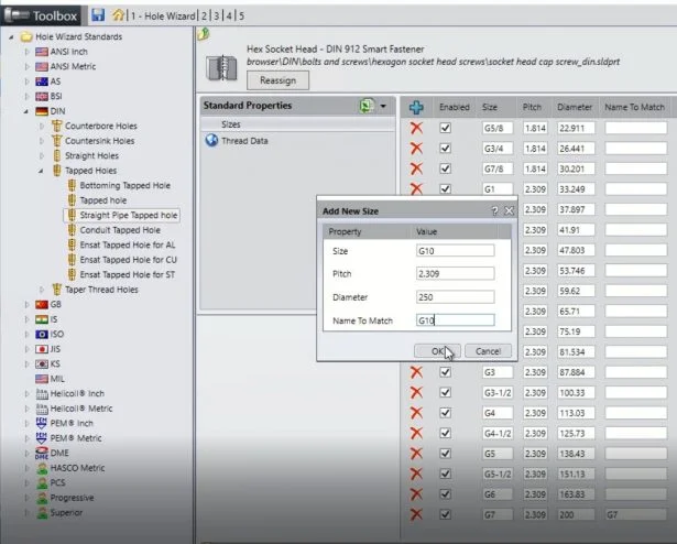
- While still in step “Hole Wizard”, navigate the tree/icons to Tapped Holes > Tapped hole
- The “Sizes” property will be selected; click the plus symbol to add a new size
- Fill out all three values for the new size. You can use the existing sizes as a template for the formatting of text and values that you need to enter.
- Save
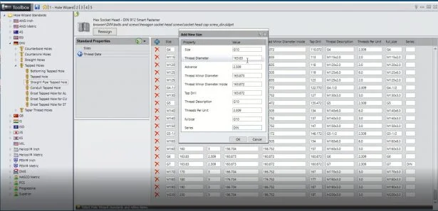
- Select the “Thread Data” property
- Again, click the plus symbol
- Fill out all ten values if the size does not already exist, making sure that the corresponding size values match EXACTLY with the size values entered in step 7
- Save
- Go to your part where you need to add a stud with the “Stud Wizard”
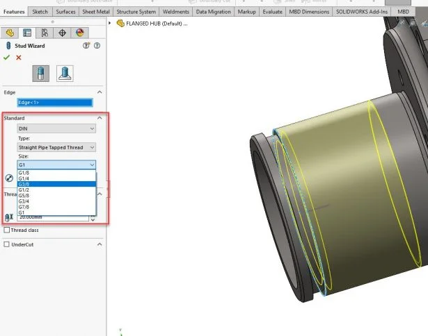
- Start the “Stud Wizard” command and in the dialog select the standard, e.g., DIN
- Specify the type of thread, e.g., “Straight pipe tapped thread” and the “Size” drop-down list should be populated with the custom size you have added.
- Select the custom size to apply the stud.
NOTE: For newly added data to populate in the list, we have to add the data in both ‘Sizes’ and ‘Thread data’ sheet.
The stud has also additional parameter – “UnderCut”.
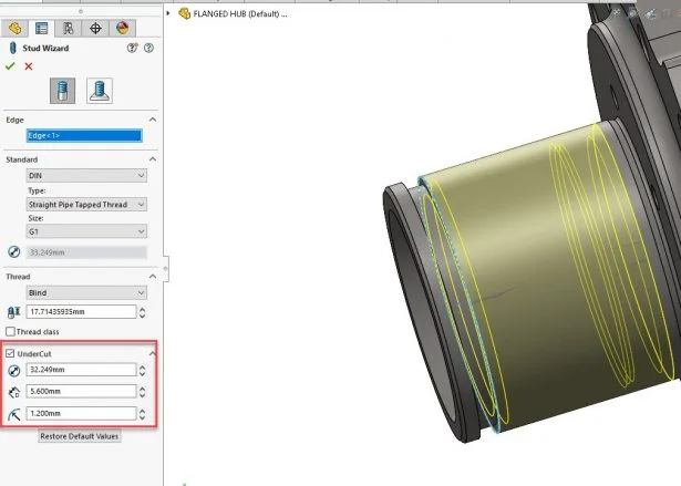
The undercut data is not visible in the Toolbox application. But we can see them by opening ‘swbrowser.sldedb’ in SQLite DB browser.
In this table, the we have 6 different records for undercut:
For AI – “AI_DATA_UNDERCUT”;
For AM TappedHole – “AM_DATA_UNDERCUT”
For AM StraightPipeTap – “AM_DATA_UNDERCUT_PIPE”
For DIN ConduitTap – “DIN_DATA_UNDERCUT_CONDUIT”
For DIN StraightPipeTap – “ISO_DATA_UNDERCUT_PIPE”
For all the rest – “ISO_DATA_UNDERCUT_METRIC”
Note : If the values inserted in the new sizes are such that they cannot create a correct sketch with the proper undercut from this table, the stud will not be created and will fail.
SOLIDWORKS® ‘Pack and Go’: Commonly asked queries
By Gaurav GAYAKWAD
Many a times we get questions related to Pack and Go which gets us thinking about its basics. Here are some information, which should be known to users when using SOLIDWORKS Pack and Go.
Why are drawing files not included in the ‘Pack and Go’, even if option ‘Include drawings’ is checked and drawing files are showing correct part references.
- Pack and Go only includes drawing from the same folder as of components. To include drawings from the subfolder you need to turn on Pack and Go/File Location ‘Include subfolder’.
- To include drawings from another folder you need to add them in the ‘Reference Documents’ location and check on the ‘Include subfolders’ option. Refer to solution ‘S-013196’ and also help document.
- Sometimes this basic is missed and can create confusion.
Why my drawing files which are saved at other locations, are not getting included in Pack and Go, even if I add the location in the ‘Reference Documents’ file location?
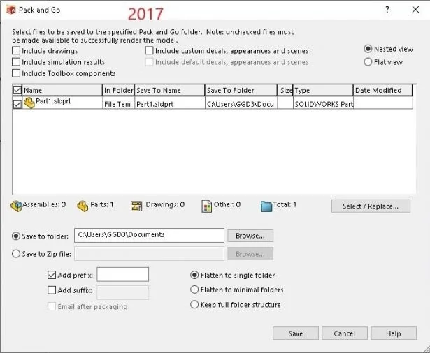
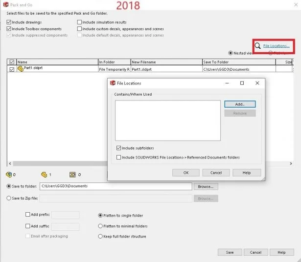
- Since SOLIDWORKS 2018 there is new functionality added (‘Include subfolders’) which gives liberty to the user that he can add or leave the drawing files which are in the sub-folders or totally separate folder on disk. So to answer the question you need to check on ‘Include subfolders’ as well. Until SOLIDWORKS 2017 you just needed to add the location in the ‘Reference Documents’ file location. Below are the images for the 2017 and 2018 versions of Pack and Go
- All this creates confusion because when a normal user clicks on ‘Include drawings’ his expectation is to include all the drawing files in different folders which has reference to the opened component. There is an enhancement request for this, SPR 1080040 (Summary: “Indicate in the Pack and Go Interface that the Include Drawings option can only check drawings in active folders and referenced file locations”)
Even after turning on ‘Include subfolders’, why my drawings are not included?
- It can be the case that the user has turned on ‘Include subfolder’ from Tools > Options > External References.
- They need to turn on ‘Include subfolder’ from Pack and Go/File Location
SCENARIO CREATION: The following observations were made during a test with different scenarios :
I have used four files to investigate this issue.
- Assem1.SLDASM – Top level assembly
- Part1.SLDPRT – Part inserted in ‘Assem1.SLDASM’
- Assem1.SLDDRW – Drawing of assembly file ‘Assem1.SLDASM’
- Part1.SLDDRW – Drawing of part file ‘Part1.SLDPRT’
I have created two different folders ‘Folder 1’ and ‘Folder 2’ parallel to each other on the local disk and saved the above files in the following way.
Scenario 1
- Assem1.SLDASM – Folder 1
- Part1.SLDPRT – Folder 2
- Assem1.SLDDRW – Folder 2
- Part1.SLDDRW – Folder 2
Notice here that the part file and part drawing file is in the same folder (Folder 2) but the assembly drawing file is in another folder with respect to assembly.
Follow the below steps now.
- Open ‘Assem1.SLDASM’ in SOLIDWORKS 2022.
- Go to File > Pack and Go > Check on ‘Include drawings’ > Check on ‘Include Subfolder’.
- Following will be the result.
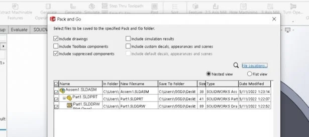
Here the query arises, why did only the part drawing file got included in the Pack and Go and not the assembly drawing?
- This is because the assembly drawing file is in a different folder from the assembly so we need to add the location in the ‘Referenced Documents’ file location.
- So for any drawing file which is not in the same folder or subfolder. You need to add the location in Reference Document.
- Similarly, the result varies for the following scenarios.
Scenario 2
- Assem1.SLDASM – Folder 1
- Part1.SLDPRT – Folder 1
- Assem1.SLDDRW – Folder 2
- Part1.SLDDRW – Folder 2
Scenario 3
- Assem1.SLDASM – Folder 1
- Part1.SLDPRT – Folder 1
- Assem1.SLDDRW – Folder 2
- Part1.SLDDRW – Folder 1
These scenarios can also help you to understand what is the expected behavior while working with Pack and Go with a complex folder structure.
3DEXPERIENCE Marketplace add-in for SOLIDWORKS®
By Kiran Digidigi
3DEXPERIENCE® Marketplace is source of qualified ecosystem of industrial suppliers worldwide for on-demand manufacturing and intelligent part sourcing. 3DEXPERIENCE Marketplace add-in is free tool for SOLIDWORKS, Marketplace can be accessed easily by login using 3DEXPERIENCE passport credentials or MySolidWorks credentials.
Let’s see how to download, install and use 3DEXPERIENCE Marketplace add-in within the SOLIDWORKS.
- Download and Installation of 3DEXPERIENCE Marketplace add-in.
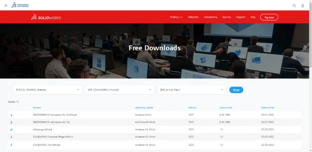
- 3DEXPERIENCE Marketplace add-in can be downloaded from 3DEXPERIENCE Marketplace
- Go to downloaded location, double click on the files to Unzip and install.
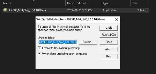
- Give permission to install and continue to complete the installation.
- Once installation completes, it will show in SOLIDWORKS add-ins section.
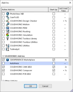
- 3DEXPERIENCE Marketplace add-in can be downloaded from 3DEXPERIENCE Marketplace
- How to use 3DEXPERIENCE Marketplace.
- Go to 3DEXPERIENCE Marketplace in SOLIDWORKS task pane, and click ‘Let’s get started’.
- Login window pops up, login with 3DEXPERIENCE passport credentials or MySolidWorks account credentials, and continue with ‘Let’s get started’.

- There are two tabs in main page of 3DEXPERIENCE Marketplace:
- As a System of Operations: Allows users to browse available applications in 3DEXPERIENCE Platform for particular industry in the form of categorized roles.
- As a Business Model: Where users can use full capabilities of 3DEXPERIENCE Marketplace. In this section there are three categories.
- Engineering: Engineering as a service is a most seamless way to Digitize, Design or Certify your Products with leading engineers worldwide. Users can find service providers, and send their requirement. Also can become a Dassault Systèmes Engineering Partner.
- Make: Manufacturing as a service is an online on-demand manufacturing platform operated by Dassault Systèmes. It connects the industrial ecosystem of Designers, Engineers, Buyers and Production planners with industrial manufacturing service providers. To know more about 3DEXPERIENCE Marketplace | Make, please refer the Making a Part with the 3DEXPERIENCE Marketplace SOLIDWORKS Tech Blog.
- PartSupply: Components as a service, is the most comprehensive and intelligent catalog of sourceable 3D components. The 3D components you need, at your fingertips for free. Search catalogs and insert components within your design environment.
Boost your productivity with ‘CustomBlock’ in DraftSight®
By Punam Mahadik
As a DraftSight user, we are quite familiar with the “Block”. However, DraftSight 2022 has come up with more advanced development of it i.e. “CustomBlock”. The Standard block is a stationary block, whereas the CustomBlock has enhanced features, which let you define rules and constraints to control the shape, size, or appearance of it in drawing.
Real-life items represented by blocks can always be made into multiple variations, such as different sizes, shapes, orientations, and configurations. These variations led to a large number of separate blocks and DWG files, which are usually hard to manage and take up a lot of storage space. CustomBlocks can greatly reduce standard blocks and file quantities resulting in saving dozens, hundreds, or even thousands of files.
The common workflow/procedure to create a CustomBlock is:
- Plan the CustomBlock in advance
- Define the Block
- Open the Block in the Block Editor
- Add elements
- Assign activities
- Test the CustomBlock
- Save the CustomBlock
Now, let us take a simple, practical example to see how to create a CustomBlock.
- Plan the CustomBlock in advance: Before creating a CustomBlock, carefully consider what you want to create. In this article, we will create an ‘Office cupboard’ configuration with multiple drawers/compartments.
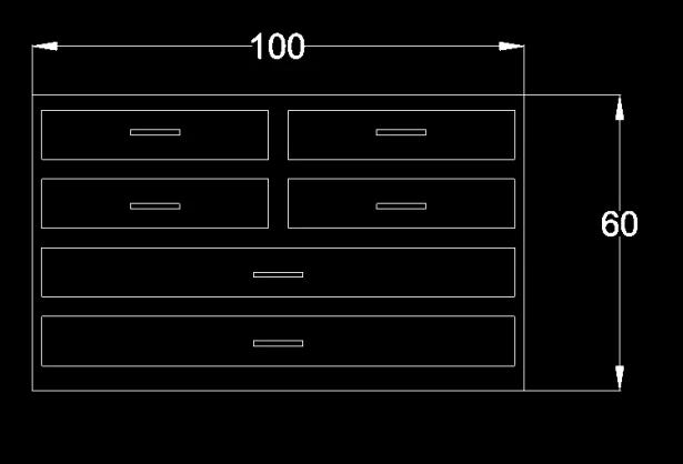
- Define the Block: First, create a basic block geometry. Draw a 100″ x 60″ rectangle to represent the outer frame of the cupboard. As shown in the image below, draw the inner rectangles (Drawers along with the handles) by taking the appropriate dimensional proportions.Define this geometry as a block by using the ‘MakeBlock’ command.
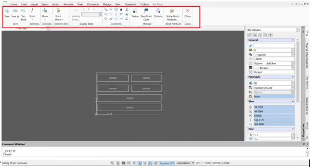
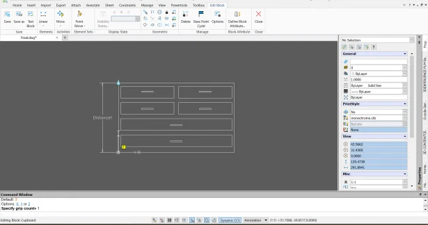
- Open the Block in the Block Editor:The Block Editor provides all the tools you need to create and modify CustomBlocks. Double click on the block or use the command ‘EditBlock’ to open the block in the block editor environment.
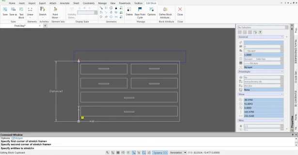
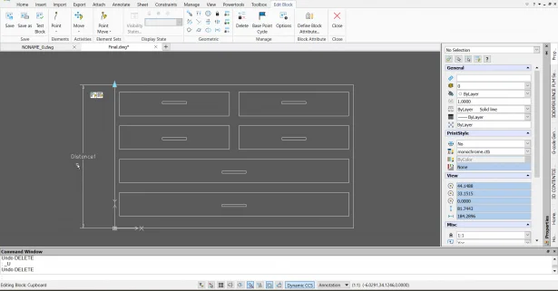
- Add Element: Here, we will add a linear element across the height of the cupboard.Follow the below steps to add an element to the entity:
- Go to ‘Edit Block’ ribbon tab > Elements > Inside the drop-down menu, select ‘Linear’
- Specify the Start point by clicking on the lower left corner of the outer rectangle.
- Specify the endpoint by clicking on the upper left corner of the outer rectangle.
- Specify the location to place the label of the element.
- Note : The “exclamatory”

mark near the element indicates that ‘The activity’ is yet to be assigned to this element.
- Note : The “exclamatory”
- Go to ‘Edit Block’ ribbon tab > Elements > Inside the drop-down menu, select ‘Linear’
- Assign activity : Now, we will need to assign two activities to get the different configurations of the cupboard: 1. Stretch activity: To extend/increase the height of the cupboard – 2. Pattern activity: To increase the number of drawers in the cupboard.Follow the below steps to assign these activities to the element:
- Assign Stretch activity
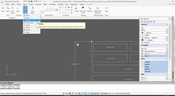
- Go to ‘Edit Block’ ribbon tab > Activities > Inside the drop-down menu, select ‘Stretch’.
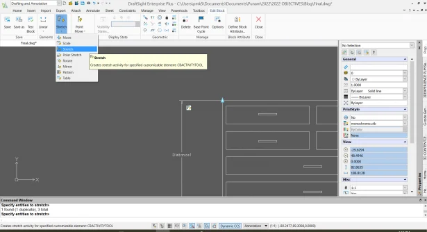
- Specify the element by clicking on the linear element created in the 4th Step (Add element).
- Specify the element point (Grip point) associated with the activity by clicking on the upper left corner of the outer rectangle.
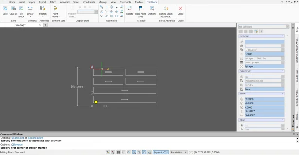
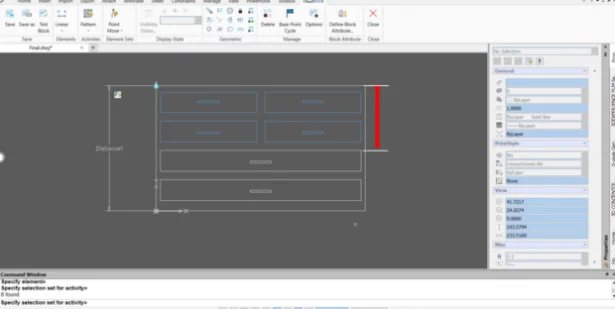
- Specify the first corner of the stretch frame by creating the window (Highlighted in a blue rectangle) as shown in the image.
- Specify the second corner of the stretch frame by creating the crossing window (Green colored) and press Enter to finish the operation.
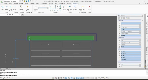
- The activity is assigned to the element and the symbol of the stretch activity

created near the respective element.
- The activity is assigned to the element and the symbol of the stretch activity
- Go to ‘Edit Block’ ribbon tab > Activities > Inside the drop-down menu, select ‘Stretch’.
- Assign Pattern Activity
- Go to ‘Edit Block’ ribbon tab > Activities > Inside the drop-down menu, select ‘Pattern’.
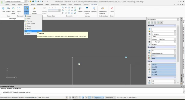
- Specify Element by clicking on the linear element created at 4th Step (Add element).
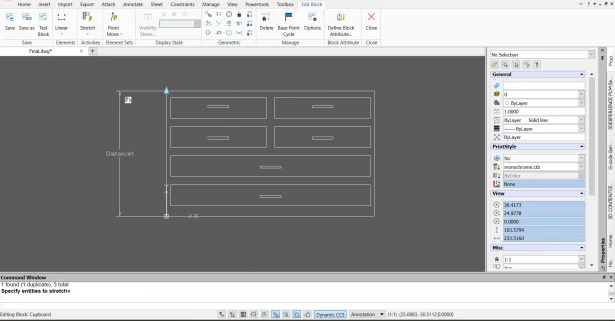
- Specify the selection set of activities by selecting the top 4 drawers.
- Specify the distance between columns (Enter the value of the distance highlighted in Red) and press Enter to finish the operation.
- Now, Stretch and Pattern, both the activities assigned to the element and the symbol of the activities created near the respective element.
- Now, Stretch and Pattern, both the activities assigned to the element and the symbol of the activities created near the respective element.
- Go to ‘Edit Block’ ribbon tab > Activities > Inside the drop-down menu, select ‘Pattern’.
- Assign Stretch activity
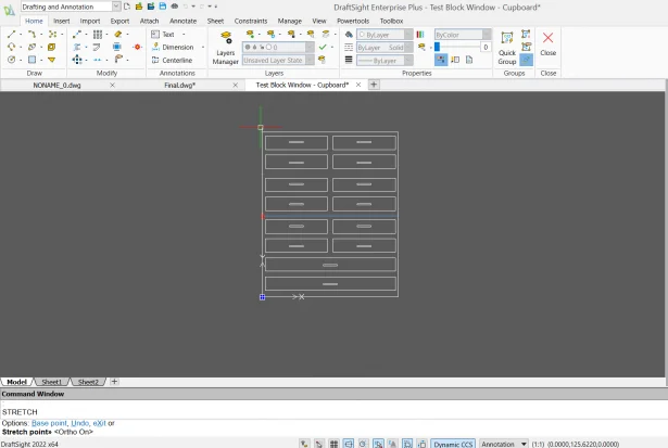
- Test the CustomBlock: You can test a CustomBlock at any time without exiting the Block Editor and saving the CustomBlock. Follow the below steps to test the CustomBlock:
- To display the current Block definition in a test window, go to ‘Edit Block’ ribbon tab > Save > Click on ‘Test Block’. Note: You can also use the ‘CBTestBlock’ command.
- In the Test block environment, to test the created CutsomBlock Hold the grip point at the upper left corner and drag it upwards and you will see the number of drawers are increasing in the cupboard.
- Use the ‘CBTestClose’command to close the test window.
- Save the Custom Block:
- You can save a CustomBlock: definition for later use within a drawing.To save the CustomBlock, use ‘CBSave’ and ‘CBSaveAs’ commands.In addition, you can use the ‘CBWBlockAs’ to save the CustomBlock as a separate drawing.
In this way, by using activities such as show/hide (Visibility states), stretch, move, rotate, mirror, pattern, scale, and table in a CustomBlock, you can integrate multiple variations into one single drawing. Try creating a variety of CutomBlocks by using the basic ‘7-step workflow’ and experience the magic of it to boost your productivity.
Noteworthy Solutions from the SOLIDWORKS® Knowledge Base

How do I obtain balanced forces on parallel motors in SOLIDWORKS® Motion? A common behavior that typically happens on symmetrical models with two motors or actuators working in parallel is that one of the motors takes almost all the load. For more information see solution ID: S-079781

Can I combine the cut list properties into one string within the cut list properties window? For more information see solution ID: S-079648

How do I troubleshoot the SOLIDWORKS® Manage notification service? The SOLIDWORKS® Manage notification service usually polls every 30s or 60s for notifications to send. For more information see solution ID: S-079784
What version year and service pack of SOLIDWORKS® supports Windows® 11? Support for Windows® 11 starts with SOLIDWORKS® 2022 SP02. For more information see solution ID: S-079805