

Hello to all,
Welcome to the new edition of the SOLIDWORKS® Support Monthly News! This monthly news blog is co-authored by members of the SOLIDWORKS® Technical Support teams worldwide.
How to obtain balanced forces on parallel motors in SOLIDWORKS® Motion?
By Julien BOISSAT
A common behavior that typically happens on symmetrical models with two motors or actuators working in parallel is that one of the motors takes almost all the load. The other motor barely takes any load, or no load at all. This behavior opposes expectations that there are balanced forces on parallel motors. Despite this apparent conflict, the behavior in SOLIDWORKS® Motion is normal and expected.
SOLIDWORKS Motion considers all bodies perfectly rigid. This is typical for motion analysis software, and not unique to the SOLIDWORKS® Motion product. In addition, motors have infinite power. They are essentially motion drivers.
When two identical motion drivers work in parallel to set a single body in motion, this creates a redundancy. It is impossible for the motors to share the workload equally. The infinite stiffness of the rigid bodies mandates that either motor takes the load in its entirety. This limitation is inherent to rigid body dynamics.
In the real world, all bodies are flexible and the motors take their share of the load.
Note: This is the same reason that in a motion simulation, a door on two hinges has a reaction force only on one of the hinges. For more information about redundancies and the example of the door on hinges, see Solution ID: S-019755 – “Redundancies in Motion Simulation.”
To overcome this limitation, introduce some flexibility in the system.
A method that sometimes works is to replace some mates with bushings. It requires adjusting the stiffness of the bushing appropriately, and sometimes modifying the Advanced Options of the Motion Analysis. This process is iterative, and it is not always reliable.
A reliable method is to replace motors with forces that have a magnitude defined with an expression. This generic method can help resolve a wide variety of situations. You can also use it to make a point of a part to follow a known path at a specified velocity. See Solution ID: S-019402 – “How to make a point of a part follow a known path at a specified velocity.”
The following example illustrates the method of resolution using forces. You can download the model from the attachment to Solution ID: S-079781.
Example :
Consider a frame with hinges on the right hand side. Two actuators on each side lift the frame simultaneously at a constant velocity of 50mm/s.
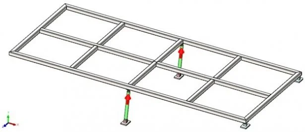
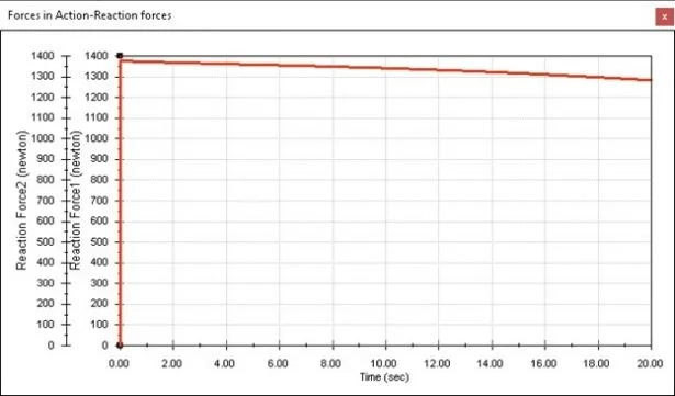
If you define two motors to drive the motion of the actuators and run the simulation, this is what you obtain:
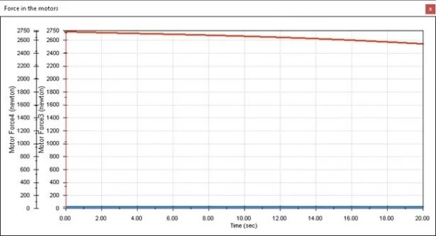
As you can see, one of the motors takes almost all the load (about 2750N), while the other barely takes any load. Note the vertical axes of this plot have a custom matching scale to allow a visual comparison of the motor forces. To make each actuator take its share of the load, a good method is to replace the motors with forces that have a magnitude defined with an expression. The expression is such that the magnitude of the force adjusts to obtain the desired constant velocity of 50mm/s. The expression therefore involves a Motion Study Result. It is imperative to define the appropriate result plot before defining the force.
Here is a sample procedure:
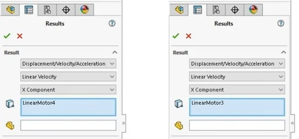
1. Copy the existing Motion Study with the motors. 2. In the new study, Suppress each motor. After you suppress a motor, it is no longer effective. However, you can still obtain results from that motor. 3. Create a new result plot for the Linear Velocity of each motor. The expression of the force magnitude will use this Motion Study Result.
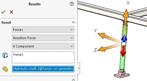
4. To replace the first motor, define a force. 5. In the Force/Torque PropertyManager, select Action & reaction force. 6. Select geometric entities of the actuator to give the appropriate orientation to the force. Be sure that you select the correct faces – avoid selecting axes. It helps to temporarily hide the outer shaft component.
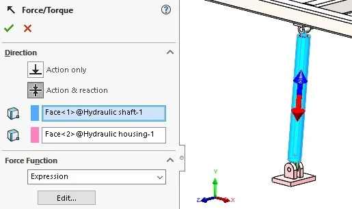
7. In the Force Function list, select Expression. 8. If you do not already see the Function Builder, click the Edit… button 9. In the Function Builder, define the magnitude using an expression. For a velocity of constant magnitude, the expression should be in the form c*(v-{Linear VelocityXXX})
Where: c is a force magnitude coefficient (in Newtons). You should try different values until a value is high enough to set the mechanism in motion and ensure the velocity of the actuator is sufficiently close to the goal (a constant 50mm/s in the current example) and is low enough to let the solvers run without problem
v is the velocity (in mm/s, or whatever your model’s velocity unit is) at which you want the part to move
{Linear VelocityXXX} is the linear velocity magnitude plot previously created for the motor that corresponds to this actuator. Select it from the list of Motion Study Results (to get there, click drop down menu in the upper right of the Function Builder which shows Mathematical Functions by default).
Therefore, the initial velocity of the force is very large c*(v-0). This sets the mechanism in motion. As the velocity of the actuator increases, the force decreases, to maintain the speed of v mm/s.
In the present case, the expression is 1000*(50-{Linear Velocity1})
Note: If the velocity you desire does not have a constant amplitude, replace c with the appropriate expression.
10. Repeat steps 4 to 9 for the second motor. 11. In order to monitor the value of the two Action & reaction forces you created, create two new Result plots of the type Force > Reaction Force. Select the appropriate force component and Component to define XYZ directions. You need the force to follow the change of orientation of the actuator.
12. Plotting the two force results on the same graph, you obtain this:
Note the vertical axes of this plot have a custom matching scale to allow a visual comparison of the motor forces.
Conclusion
The Action & reaction force that replace the motors and drive the motion of the mechanism have exactly the same force profile. Hence, the two curves completely overlap and are indistinguishable in the graph. Notice that the sum of the two Action & reaction forces is equal to the force in the original motor that was carrying the entire load.
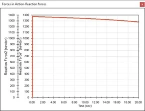
Therefore, you can see from the graphs that the goal of balanced forces on parallel motors in SOLIDWORKS Motion has been achieved as desired.
Manage your block library using Visibility States in DraftSight Custom blocks:
By Gayatri KESKAR
While working on a large .dwg file we might have noticed multiple similar blocks used for different purposes. Sometimes it can be tedious task to look for a correct block in a long list of a block library in a drawing file. Combining blocks to create a Custom block with Visibility States is a solution to this to save time and help manage content in a drawing.
One of the examples for this would the custom blocks in an architectural block library like window open, closed or open window at specific angles etc.. Using visibility states we can create single custom block for different views of window and switch between them using drop down list as we insert the block in graphics area.
Steps to add visibility parameter and create visibility states:
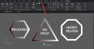
Let’s say we have 3 different blocks as shown in below image for symbols that we have created using DraftSight entities and want to combine them in single custom block.
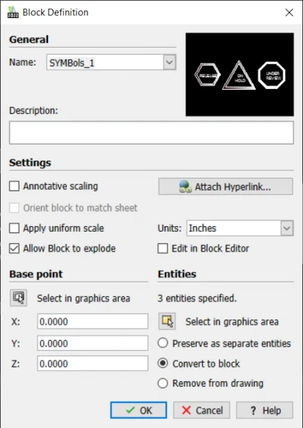
1. Use Block command and select all 3 blocks to convert them to single block say ..SYMBols_1 2. Select newly created block in step1 and type command EditBlock to start block editing session. 3. Go to Elements>visibility and specify a point for visibility parameter which will act as an insertion point for the new custom block and will also show the icon to display the list of display states. 4. Now click on Visibility states and start adding different visibility configurations as below:
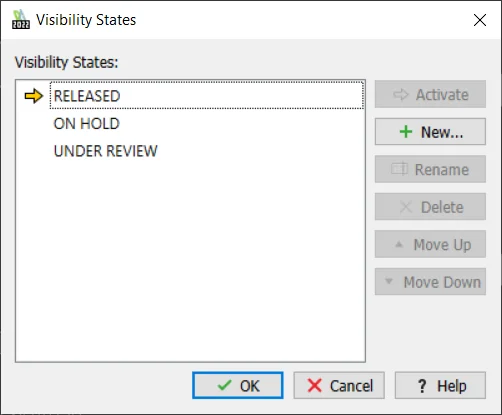
5. Activate visibility states one by one and hide the blocks that you don’t want to display in that state by selecting hide button:
6. Test the block to check if it’s working as expected.

This way we can create multiple custom blocks combining similar blocks and manage content in a drawing file effectively. It is a very efficient way to save time and reduce the data in a drawing file.
Visualize: From scratch to creating a scene – Water Droplets on the Salt Flats
By Camille JOHNSON
I love a little bit of rain on a hot day, especially when it is very dry out most of the time.
In today’s blog post, we will learn how to create a water droplet in just a few mouse clicks. After creating the droplet in SOLIDWORKS® CAD software, we will import the model into SOLIDWORKS® Visualize Professional with just a few more mouse clicks and start creating this image:

Step 1: Create a water droplet.
This step is left up to the user. Be creative, make a weirdly-shaped water droplet if desired, or stick with a quick spline and revolve feature. Once complete, continue to Step 2.
Step 2: Import the model and set the scene.
If you have arrived at this step, congratulations! You made a rain drop in SOLIDWORKS®!
You will start this step by opening SOLIDWORKS® Visualize. Once it has launched, begin a new project and start importing the geometry:
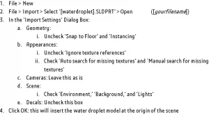
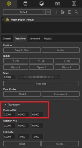
As you will notice when inserting the water droplet model, part of the model is occluded by the floor. This is because of how we defined the two planes when creating the model in SOLIDWORKS®. The origin of the SOLIDWORKS® Visualize scene is coincident with the origin of the SOLIDWORKS® model. However, this is an easy fix by either of the following steps:
Option 1:
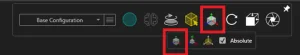

Option 2:
Next, I’ll explain how to set an environment and a backplate. This is where the image of the salt flats comes in.
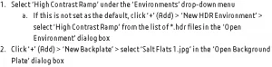
To set an environment for your rendering, direct yourself to the ‘Scenes’ tab on the SOLIDWORKS® Visualize Palette.
This is what your SOLIDWORKS® Visualize project should look like once you’ve applied those settings:

Step 3: Apply Appearances to the water droplet model
We’re almost there, we just need to apply some appearances to the water droplet itself and I have found that adjusting the settings on some premade appearances works great for this cause.
First, we’ll navigate to the ‘File Libraries’ tab in the palette, and then take the following steps:
- Select ‘Appearances’ from the drop-down box > ‘Liquid’ > select ‘Lemonade’ and drag and drop it onto the water droplet model : This will change the water droplet’s appearance to a nearly transparent appearance.
Next, I’ll explain how to change some settings to make it look more like a water droplet.
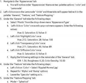
Your water droplet is finished! You may copy instances of this model and resize and relocate them as you desire!
Noteworthy Solutions from the SOLIDWORKS Knowledge Base

What are the known compatibility issues between SOLIDWORKS® 2022 SP02 and Windows® 11?To get more information, see solution ID: S-079806
When I right-click a part, drawing or assembly file, why does the SOLIDWORKS® file utility label not appear?This problem could happen after a Windows® or SOLIDWORKS® update. To get more information, see solution ID: S-079838

When I use the SOLIDWORKS® PDM quick search or integrated search functionality, why do the SOLIDWORKS file open or save dialog boxes stop responding (hangs or crashes)?This problem can happen on a SOLIDWORKS® PDM client workstation if the file type associations for SOLIDWORKS files are incorrect. To get more information, see solution ID: S-079778

What can I do if every SOLIDWORKS® Flow Simulation project I run shows a ‘Preparing model’ Solver Monitor status indefinitely and any FloXpress analysis never finishes the ‘Meshing in progress’ step?To get more information, see solution ID: S-079776