

Hello to all,
Welcome to the new edition of the SOLIDWORKS Support Monthly News! This monthly news blog is co-authored by members of the SOLIDWORKS Technical Support teams worldwide.
Think Smart – Use ‘Smart Components’ in SOLIDWORKS
By Akhil C
When it comes to creating an Assembly, inserting few components may require some additional features and components to accompany them. Recreating these additional components and features every time turns out to be a tedious task for the user.
For example, if one wants to mount a ‘door handle’ on a ‘door’ Assembly, he would necessarily require fasteners and holes to mount the handle on the door. A smarter way – Make ‘Door Handle’ smart!! When this smart ‘Handle’ in inserted in assembly, it will bring in the fasteners(components) and introduce holes (features) on the door. In this case, the user will save the time required for 1. Making holes on the door, 2. Inserting required fasteners, 3. Assigning the necessary Mates. In situations similar to this, such solutions are a big time savior. Now imagine huge assemblies with several such components. This would work as a charm for the users.
Making a Component ‘smart’ and using it in the required assembly can bring in all the required parts, sub-assemblies and features associated with it in just few clicks.
Without wasting much time let’s move on to see how can you make a component ‘Smart’ and use them in your assembly. Here a portion of ‘Guitar Assembly’ is considered as an example to explain the functionality ‘Make Component Smart’. Few components are named and shown in the ‘figure A’ for reference. In this example we will make ‘Bridge’ a smart component and use in another assembly to demonstrate the functionality.
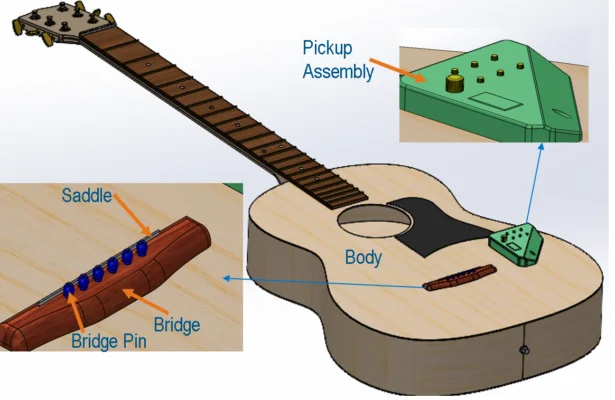
Figure A
First and foremost step is to create a ‘Defining Assembly’:
This can be seen as a way of telling components, what relations/positions has to be maintained with other components when used in another assembly. This assembly should contain:
- Component which has to be made ‘smart’ – ‘Bridge’ in this example
- Components (Parts/subassemblies) which has to accompany ‘Smart Component’ – Saddle, Bridge Pins and Pickup.
- Components whose features has to accompany ‘Smart Component’ :Body ( as features such as holes and slot from ‘body’ will be associated to ‘Bridge’)
These components should be correctly positioned in the assembly created and required mates should be defined. As shown in figure 1.1, Bridge, Saddle, Bridge pins and Pickup Assembly are positioned as required and mates are correctly defined.
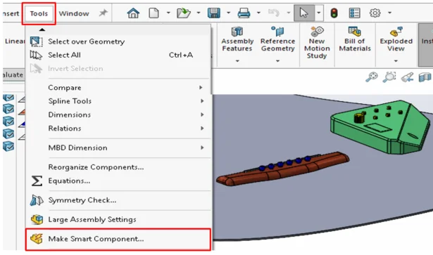
Figure 1.1
Next step is to make the component a ‘Smart Component’:
To do this select functionality ‘Make Smart Component’ under ‘Tools’. This will open the ‘Smart Component’ PropertyManager. In PropertyManager :
- Under ‘Smart component’ you have to select the component that has to be made smart.
- Under ‘Components’, select Components (Parts/subassemblies) which has to be associated to the smart component and,
- Under ‘Features’, select the features that has to be associated to the smart component.
- Click OK (Green tick in PM) and save the assembly.
Moving to our example , in PropertyManager we will select (see figure 2.1):
- ‘Bridge’ under ‘Smart Component’
- Saddle, ‘Bridge Pins’ and ‘Pickup’ Under ‘Components’.
- ‘Holes’ and ‘cut-extrude’ on ‘body’ under ‘Features’
- Click OK (Green tick in PM) and save the assembly.
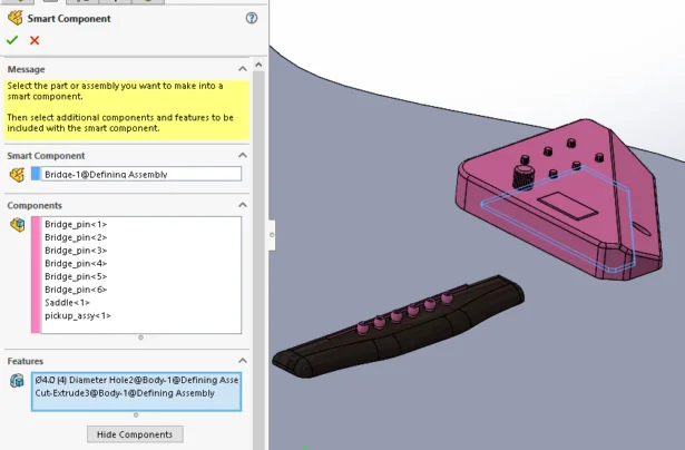
Figure 2.1
Great..!! ‘Bridge’ is now a ‘Smart Component’. You will observe a flash symbol next to the component (Bridge) in the design tree, which means the component is now a ‘smart component’. Apart from this, a folder named ‘Smart Feature’ is added in component design tree which lists all the associated components, feature and references (see figure 2.2). Deleting this folder, turns the component back to normal.
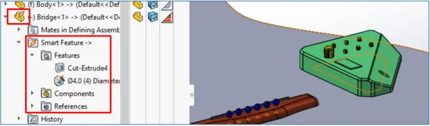
Figure 2.2
Using this ‘Smart component’ in Assemblies:
Once a component is made ‘Smart’, you may start using it in your assemblies. Insert this ‘smart component’ in an Assembly and position/mate as needed. Next step is to activate/call the associated components and features into the assembly. You may activate the associated components by one of the three ways mentioned below :
- Select the smart component from design tree and click on flash symbol displayed over the ‘smart component’ in graphics area, OR
- Right-click ‘Smart component’ from design tree > ‘Insert smart features’, OR
- Expand ‘Smart components’ from design tree > RMB ‘Smart Feature’ folder > RMB ‘Insert’. .
This will open the ‘Smart Feature Insert’ PropertyManager. In PM you can Select components and features to bring in from the list.
Further, under references, you need to select references for each listing. A window will appear, which will highlight the references required as set in ‘Defining Assembly’. For example : On which face ‘Cut-Extude’ has to be placed? Once done, this will bring in all the selected associated parts/subassemblies and features from the ‘Defining Assembly’.
Let’s follow this step in our example. We will insert our Smart component ‘Bridge’ in another assembly ‘Main.sldasm’ and position it as required. As we select the ‘Bridge’ from design tree, flash symbol appears in the Graphics area over the ‘smart component (figure 3.1).
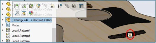
Figure 3.1
Clicking on this button opens ‘Smart Feature Insert’ PropertyManager. In PM we can observe that under ‘Features’ and ‘components’ are the listings which we selected from the ‘Defining assembly’. Under References, we need to specify the required reference for features.
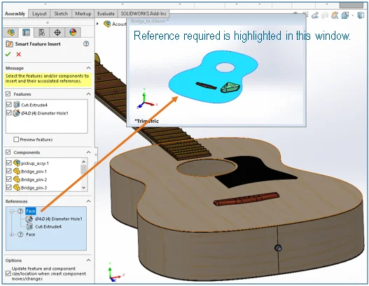
Figure 3.2: Reference need to be selected for Placing Hole and Cut-Extrude
Each reference required (As defined in ‘Defining Assembly’) will be highlighted in the preview window as shown in the (figure 3.2). As highlighted, let us select the top face of the body to place the 4mm hole and cut-extrude feature. Once done, a green check mark will be shown (under references) which means, references for that specific features/ components are now correctly defined (figure 3.3)
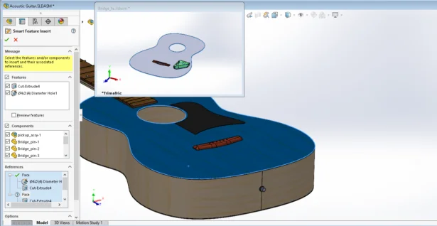
Figure 3.3: Top Face selected as reference (Observe green check mark)
Once all references are selected correctly, we are done. Say Ok in PropertyManager.
As shown in figure 3.4 all the components and features are inserted along with the ‘Bridge’ (The smart component) and in position as they were positioned/defined in the ‘Defining Assembly’. Observe the features (Holes and cut- extrude) in the Exploded view in figure 3.5.
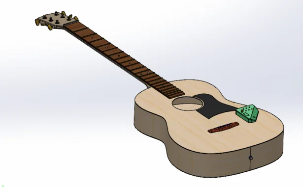
Figure 3.4 (All components/ Features are inserted correctly)
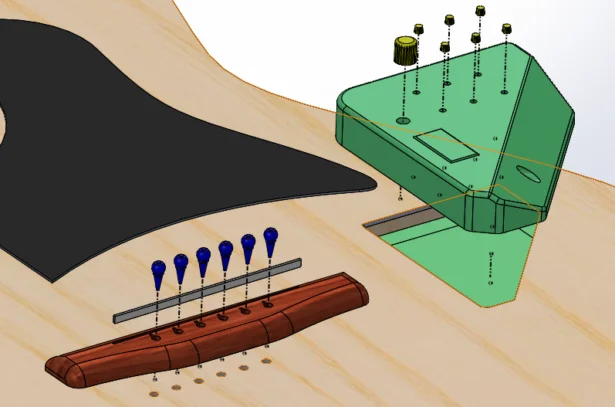
Figure 3.5 (Exploded view to show all components/ Features inserted)
Note: Use of Mate References can improve the workflow and makes the tasks easier.
These are few KB solutions you will find helpful while working with Smart components:
- S-054601: Why are some ‘Mates’ of a ‘Smart Component’ not inserted with the ‘Smart Feature?
- S-04702: After making a pattern of a smart component in an assembly, all smart features are not included in the pattern instances. Why?
- S-078226: After saving and then reopening an assembly, why do I not see the features I applied on a part or subassembly by using the Smart Component functionality?
- S-029819: How is a smart component turned into a regular component in an assembly?
- S-044365: How can the position of the fixed components in smart components be maintained? They were set to ‘fixed’ in the original defining assembly, but are now floating in the target assembly.
Equations in Assemblies- Part 1
By Mario Iocco
The equation syntax for references between assembly components loads automatically when you select dimensions, features, and global variables in FeatureManager design tree, the graphics area, File properties and the Equations dialog box.
Existing equations that do not follow this syntax are marked as errors because they create inconsistent results. You need to edit these equations to correct the syntax.
In the following example, A1 is a sub-assembly of A2 containing P1 and P2:
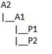
GV1 and GV2 are global variables in the documents. Use the following syntax:
Please refer to this Video for visual demonstration.
Easy SOLIDWORKS PDM data card mapping using DraftSight Blocks & Attributes!
By James Falconer
DWG files are one of the most popular filetypes that SOLIDWORKS PDM manages within a vault. Both SOLIDWORKS PDM Standard and PDM Pro give you the ability to manage these files using Windows Explorer.
SOLIDWORKS PDM can map PDM variables to attributes found within blocks. What makes PDM even more powerful is that it makes it very easy to map. By using this guide you should be able to easily understand how links are made and you should be able to create and utilize them within minutes.
What are DWG Blocks and Attributes?
A block is a collection of objects. These objects can vary in type, but for PDM purposes we concern ourselves with the object type named attribute. An attribute can store data such as names, numbers, and values. In simplest terms a DWG block is a collection of attributes.
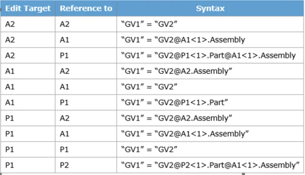
If you are familiar with PDM variables, then you should already know the term Block and Attribute! As seen in the image below the default presentation of the variable ‘Project number’ already has mapping defined for a block named DWG_TITLEBLOCK that contains the attribute PROJECT. Note how Block name and Attributes are the building blocks of all variables within a PDM vault!
A quick example on how to create a PDM data card mapping to a DWG file
- Create a new DWG file using DraftSight and save into a PDM vault
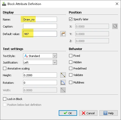
- Use the ATT command to add an attribute to the drawing named ‘Draw_no’ with the default value of ‘987’.
3. Use the BLOCK command to create a block, and select the attribute we just created (which shows as DRAW_NO).
4. Give the block the name ‘Title_1’.
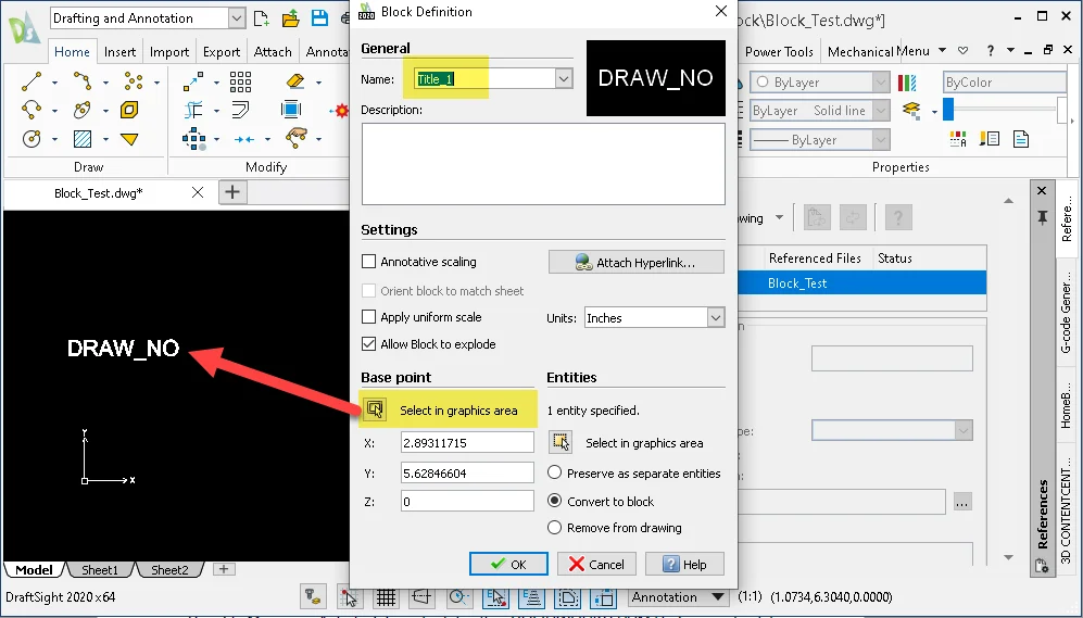
5. Save the DWG file.
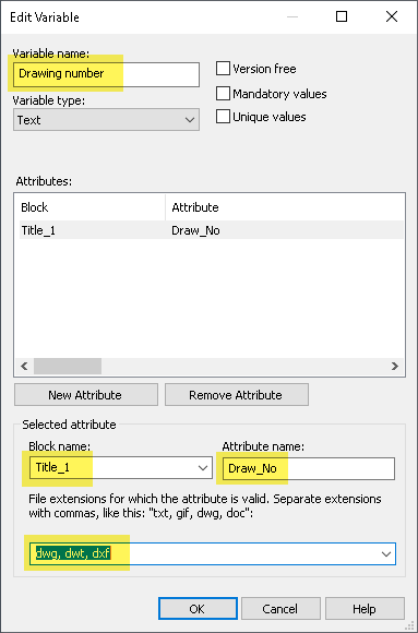
6. Open the SOLIDWORKS PDM Administration tool, and create a variable named Drawing number.
7. Click New Attribute.
8. Under Selected attribute:
a) For Block name, select Title_1.
b) For Attribute name, type Draw_No.
c) Select the DWG filetypes extensions, separated by commas.
9. Click OK.
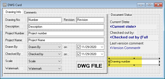
10. In the Card Editor, open the DWG file data card.
11. Add an edit box and select the new Drawing number variable as the Variable name.
12. Save the card and close the Card Editor.
Once you check in the DWG file the attribute value ‘987’ will be displayed in the DWG data card model tab.
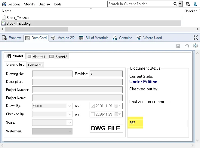
Check out this file and modify the data card field to 988, then save the card. Open the DWG file in DraftSight.
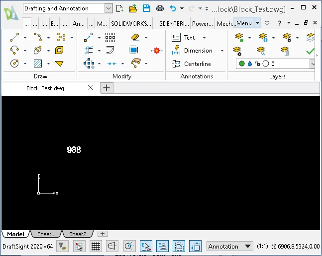
Note that the mapped attribute will have been updated to 988.
Further information
The example shown above should help most users become familiar with the most common scenario. Of course, if troubleshooting a complex DWG file you should become familiar at finding Blocks, editing Blocks with more than one attribute, and avoiding pitfalls with one-to-many, or many-to-one mappings.
Fortunately the SOLIDWORKS PDM Administration Guide, Chapter 26 should cover many of the variable mapping questions you may have, which includes mapping to Block Attributes. DraftSight help will also be very helpful, especially the section named Working with Blocks, BlockAttributes, EntityGroups, and References.
Noteworthy Solutions from the SOLIDWORKS Knowledge Base

How do I use the ‘Weldment’ feature in the FeatureManager® design tree to add custom properties and propagate those properties to the weldment cut list folders? When you open a part document, you can activate the weldment environment by clicking the ‘Weldment’ feature on the ‘Weldments’ tab. This adds the ‘Weldment’ feature in the FeatureManager® design tree. To get more information, see Solution Id: S-078558
When I unsuppress a flat pattern feature, why do see the message ‘Could not find the bend table. Please select another or specify a K-factor’? This can happen when a part uses a ‘*.btl’ format bend table. To know more, please visit the solution Id: S-078568

In the SOLIDWORKS® Manage software, how do I start the ‘SOLIDWORKS Manage Email Server Service’ manually? Open the Windows® ‘Services’ app and locate the ‘SOLIDWORKS Manage Email Server Service’. If the service is not running, start the service manually. In order to have more details, please visit the solution id: S-078495
In the SOLIDWORKS® Flow Simulation software, how do solid materials transmit the sound in relation with the noise prediction? For noise prediction, all materials are effectively perfect sound insulators. In order to have more details, please visit the solution id: S-078510
That’s it for this month. Thanks for reading this edition of SOLIDWORKS Support News. If you need additional help with these issues or any others, please contact your SOLIDWORKS Value Added Reseller.
Comments and suggestions are always welcome. You can enter them below.