
*The below content is modified based on Brian Hillner’s original blog post – Quickstart Guide to Using Virtual Reality in SOLIDWORKS Visualize Professional 2018
eDrawings Pro 2020 now supports choosing your own 360˚ images as your custom environment in VR! This blog post will help walk you through the process of creating a 360˚ equirectangular image in SOLIDWORKS Visualize and adding it to your Virtual Reality scene in eDrawings Pro 2020.
Although we have not yet supported the use of 3D models for your custom environment in eDrawings Pro, this method lets you transform your 3D model environment into a 360˚ image to use as a sky in eDrawings Pro direct Virtual Reality mode
This blog post will be helpful if:
- You have a large SOLIDWORKS dataset that you want to use as your VR environment to view your model in eDrawings Pro direct VR mode. But you are concerned about performance and want an alternative solution.
- You could not find any existing 360˚ images that fit your needs and want to create your own.
This blog post will discuss:
- How to render a 360˚ image in SOLIDWORKS Visualize Pro. This Visualize step is optional, and you could alternatively source these 360˚ images from several websites (both free and paid).
- How to set the 360˚ image as your custom sky for VR mode in eDrawings Pro.
TO RENDER A 360˚ IMAGE IN SOLIDWORKS VISUALIZE PRO:
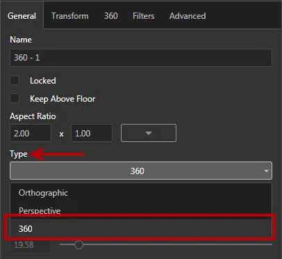
1) Create a camera by opening the Camera tab, navigating to the General subtab, expanding the Type dropdown, and selecting the new “360” option. This will automatically set your camera to the required 2:1 aspect ratio.
2) In Preview mode, you will now see a slightly wider view of your scene in the Viewport. Only Fast and Accurate (and of course PowerBoost) raytrace modes will show you the warped photorealistic final image, so you will need to use either of those modes to see how the final image will look.
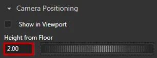
3) Using the keyboard/mouse shortcuts to Pan and Zoom, position your new 360˚ camera into the desired location. You will notice the new 360˚ camera icon next to your mouse cursor, letting you know you are moving a 360˚ camera. This 360˚ camera type is omni-directional and will always remain level (non-twisted). You can even use Multi-Viewports with another camera to drag the 360˚ camera’s manipulator manually into the desired position. Another helpful trick is to enter the desired height of the camera in the Cameras Tab > Transform sub-tab > Camera Positioning > “Height from Floor” (in meters).
A little tip for outputting to eDrawings Pro:
Let’s define a bit of terminology first. “Sky” is referring to the 360˚ equirectangular image that makes up the skydome of the VR world you see in the headset. “Floor” is referring to the default surface that we provide for you to stand on in VR.
We do not have support for transparent floors in eDrawings Pro 2020. A floor is necessary for teleportation, so you need to be careful about what part of your 360˚ image will end up being obscured by the floor.
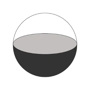
The floor will cut the 360˚ image in half by default, meaning that everything in the lower half of the 360˚ image will be shown below the floor.
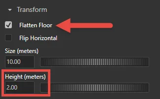
For large 3D model environment, when you are adjusting the “Height from Floor” in SOLIDWORKS Visualize, we recommend that you set the camera as close to the floor of your scene as possible. To further adjust where the floor cuts off your environment dome, enable “Flatten Floor” from the Environment tab then adjust the “Height” of the environment dome. You will then see a live preview in your Visualize Viewport. This step will help to dial in the ideal placement of your lower half, where the floor will be cut off.
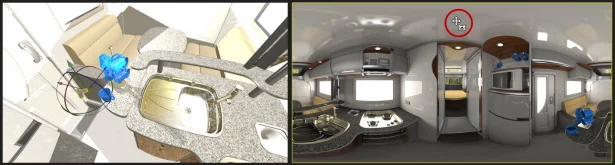
If you make these adjustments and see that the floor of your scene is located in the lower half of the 360˚ image, you will know that this 360˚ image will make a nice background for VR mode in eDrawings Pro. (Again, to see the warped photorealistic final image like below, you need to be in Fast, Accurate, or PowerBoost raytrace modes in SOLIDWORKS Visualize.)
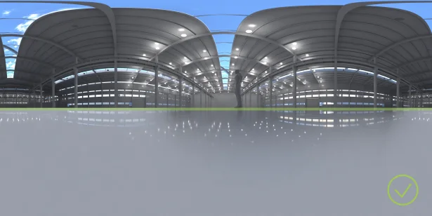
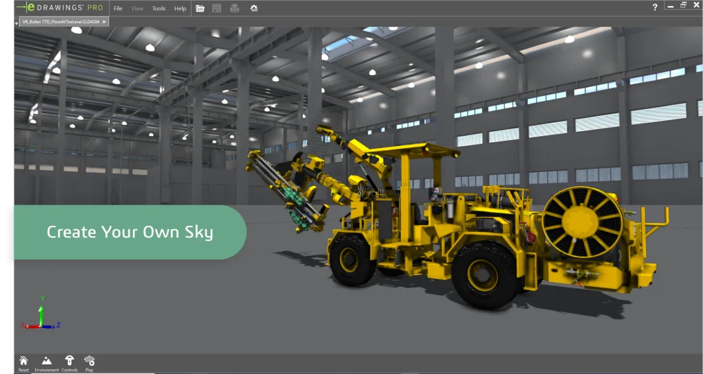
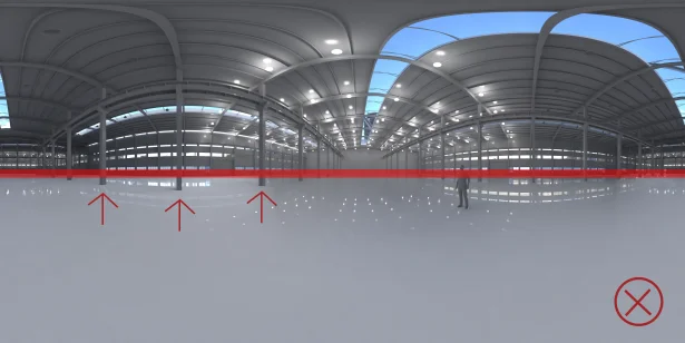
Notice how in the following case, the pillars indicated by the arrows in the image will be shown below the floor. This will make the “walls” appear to be incorrectly offset and make for a disorienting VR experience.
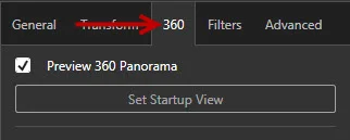
4) Once you have roughly positioned the 360˚ camera, go to the new “360” subtab in the Cameras tab and enable “Preview 360˚ Panorama”. This unique view changes your Viewport to what you would see in the final 360˚ VR experience. It’s also raytracing live, just like your normal Viewport! Use this preview to make sure your camera positioning is exactly where you want it – perfectly positioned over a seat, in the middle of the hallway, standing next to a table, etc. It is only possible to rotate the camera in this Preview 360˚ mode; you cannot move the position of the camera. Disable “Preview 360˚ Panorama” to re-adjust your 360˚ camera positioning, then re-enable “Preview 360˚ Panorama” to see the results. Repeat as necessary until your placement is just right.
Once your 360˚ camera is perfectly positioned and “Preview 360˚ Panorama” is enabled, rotate your view to where you want to start in the VR experience. Then, click the “Set Startup View” button. This sets the first view you see in the final VR experience.
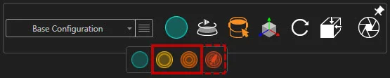
5) Turn off raytracing by selecting Preview mode from the Main Toolbar. With the new 360˚ camera active, left-click the Render button in the Main Toolbar. Select JPG as the Image Format and make sure to enable the new checkbox “Adjust for Virtual Reality playback on social media”. This ensures that you have selected the right render settings and can view your immersive 360˚ images on supported VR devices.
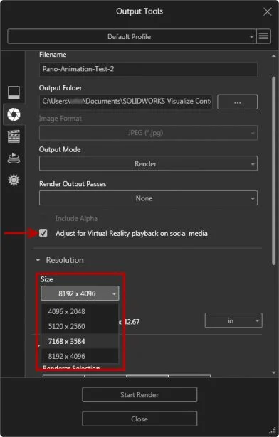
Note that a very high resolution is required for 360˚ images playback. This is because only a portion of the entire 360˚ image is visible in your viewfinder. In order to minimize any pixelization in your Virtual Reality experience, you need to select a much higher resolution. We’ve included several resolution sizes to choose from.
6) Start the render and when it finishes, see the next steps below.
TO SET THEM AS CUSTOM SKY FOR VR MODE IN EDRAWINGS PRO
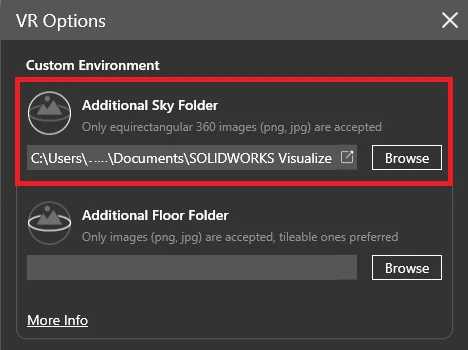
Open eDrawings Pro and go to Tools > VR Options. Here, you will be able to set the folder that you want to put your custom environments in.
In this example, the Output folder has been set to be the same path as that in SOLIDWORKS Visualize. This makes it easy to view the results generated by SOLIDWORKS Visualize in eDrawings VR without moving any files around. You can always set this destination to another location if that suits your needs better.
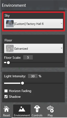
Once the destination folder is set, you can exit VR Options and open the Environment pane. Here, you can see all your custom skies and floors along with the default ones we give you, and set your environment accordingly. The environments that you add will have the label “[Custom]” included in the beginning of the name.
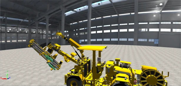
In this final image here, you can see that the pillars in our example skydome align nicely in a natural position with the floor. This is because we took care to ensure that nothing relevant to the “walls” of the factory image were located in the lower half of the 360˚ image.
Now you can enjoy your custom sky in eDrawings Pro! Can’t wait to see what you will create for your amazing VR world.