
Have you ever looked at a part and wondered if the design was over-kill or under-kill?
If you are in an industry where weight and speed are of the utmost of importance you probably try to make the lightest part possible to handle the job.
Using SOLIDWORKS Simulation Professional we can use a Topology Optimization study to take an existing part and optimize a component by setting goals for weight reduction and achieve a certain factor of safety.
One such example can be seen briefly here in our TPM Solutions YouTube Channel where we take a robot arm from a 2015 high school FIRST Robotics competition (FRC) robot and optimize the weight of the swinging arms to the load that the robot needs to be capable of lifting safely.
Each robot has a maximum weight limit of 120 pounds unloaded so every pound must be utilized carefully per the rules. Because of this constraint, teams often pocket every single part imaginable to maximize the performance of their machines.
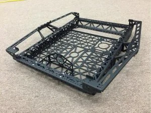
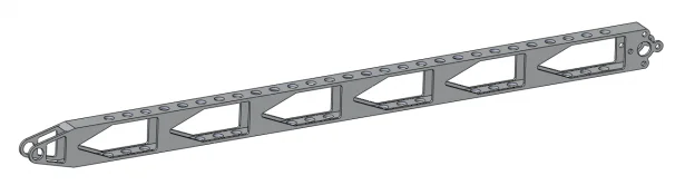
Like team 148’s robot chassis for example!
So in the case of extreme pocketing where can weight be safely removed without completely compromising the part in operation? Where can weight be removed that will leave the part virtually unaffected in operation?
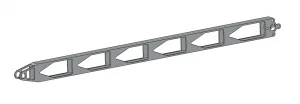
To simplify the problem we can take the robot arm made out of 2×1 tubing pictured below and run a simple static stress analysis in SOLIDWORKS to begin.
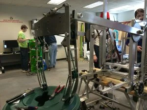
Roller claw on the two arms before final assembly.
The roller claw and game piece weigh about 15 pounds but due to some other loading conditions we assume each arm (there is one on each side) needs to resist about 20 pounds just to make sure. We treat the other end of this beam as though it were mounted through the fixed hinge fixture to emulate being held in place by the bolts and sprocket mounting pictured above.
Running a quick static stress analysis of the tube before any pocketing tells us that the tube weighs 2.4 pounds or 4.8 pounds for both arms and due to the applied load we can expect a stress of about 9,187 psi. For our aluminum material (yield strength 40,000 psi or so) this means we start with a Factor of Safety of 4.34 – Overkill!
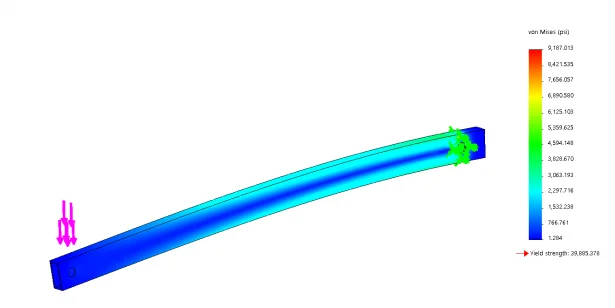
Static Stress of the arm without any pocketing.
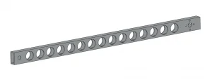
If a robot needs to lose weight most teams usually grab the trusty hole-saw bit and put the robot on a diet. At one point the robot needed to lose 15 pounds total for an additional system so we dove into SOLIDWORKS to remove material from our machine in the digital sense before we started attacking our robot with tooling.
If we remove too much weight are we going to compromise the design? That was the biggest fear factor in this challenge. We needed to know for sure that we were making the right choices so we ran another simulation and it was determined that if we had placed some holes too close to the joints that it was obvious the arms were going to fail.
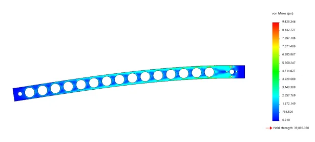
Static Stress of the arm after hole saw pocketing.
We ended up playing with the hole pattern in SOLIDWORKS multiple times to make our decision and the results were that we could reduce the mass of the part by a decent amount and get the weight of both arms down to about 3.1 pounds total. We got to an almost 40% weight savings on these two components at the end but after running a FOS check again we learned that we barely made a dent in the performance of the part at all. The FOS was 4.2 – still a huge amount of overkill. We cut hole pockets into several components, swapped to lighter panels, went with thinner tubing wall thicknesses, and moved on to win tournaments with this robot. It weighed in at 119.8 lbs out of an allowable 120 and we didn’t look back
Except I did look back. When SOLIDWORKS 2018 came out and Topology Optimization was a part of the new release I remember optimizing this particular part with my students manually in 2015 simulation and I remember the fear in their eyes as we cut that first hole on the drill press.
How lightweight could we have really made that part which is still being used on some robots in the shop even to this day?
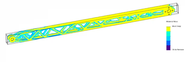
50% Mass reduction, first pass topology optimization
I ran my first Topology Optimization on this robot part and went with the goal to reduce the weight of the part by 50%. I could tell SOLIDWORKS where to leave enough material around the sprocket mount as well as the wrist where the claw attached so that the study would leave a region of material around that area. This 50% reduction laughably gave me a FOS over 3.2 still almost mocking me – no- daring me to go lower.
Challenge accepted, let’s try 75% mass reduction!
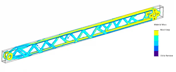
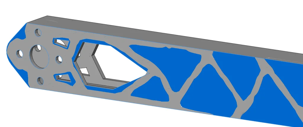
With a 75% mass reduction I ended up with a FOS of 2.1 but the geometry is very thin. Most people at this point would take the results with a grain of salt because of the lack of structure in the model but after running through this process to the end, I trust a good deal of this shape. This shape is close to the minimum required shape to take the load.
A lot of designers use triangles as their pocketing shape but the location of the triangle is of the utmost of importance for a structure like this. What this study can do for us if we are 3D printing the part is print the shape exactly as we see it but unfortunately that shape is really not a shape you would actually manufacture so what do we do with this data now?
Exporting it into a mesh body will give us a file we can manage.
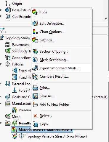
Once we bring the mesh body into SOLIDWORKS we can use a few tricks to get to a finished pocketed part and this is where the advantage of using SOLIDWORKS really kicks in.
First, there is not a lot we can do with the mesh as it exists and we cannot add design intelligence to the mesh model itself. But we can model and trace on top of it and use it as a template for where the pockets need to go. This is where we can get creative and design different pocketing styles adding fillets and additional geometry to test the effect on the factor of safety at the end.
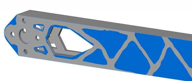
Using the mesh as a backdrop and tracing the pockets out where they need to go.
With just tracing the pockets this is the result with a 75% reduction tracing the model. The model weighs .7 pounds and still has a FOS of 2.7!
But wait, the pockets are sharp, thin, not uniform and unattractive. Learning from the topology study we can add better constraints to the model to make this a part you would care to manufacture and use.
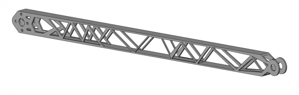
We ended up taking what we learned and applying some side loads as well as torsion loads to come up with what we felt was the lightest design based on the topology results. An arm weighing in at just .9 pounds that can handle all 3 types of loading, has an attractive pattern, and is easily machinable thanks to SOLIDWORKS Topology Studies!
Final part: .9 pounds for a total weight reduction of 63% and it will resist loading in all 3 conditions!
The Topology Study is a very powerful tool when used in this way and I hope that this inspires more users to grab SOLIDWORKS Simulation and learn about how their parts work. It was very eye opening for me to learn why most pockets were triangular in shape – that is just the way stress runs through a part from point A to B!
By: Robbie Hoyler • Elite Application Engineer • TPM