

Adding fillets to a part provides more than displaying realistic part geometry. It completes the design and may be important for manufacturing. There comes a point in which a designer may encounter an “ugly” fillet or a complex set of features that makes the fillet transitions difficult to obtain. What should you do? There are two answers; ignore it or fix it.
Defining a Ugly Fillet
At times, a complex corner can cause fillets to solve in less than aesthetically pleasing ways. Please refer to Figure 1 for an example.
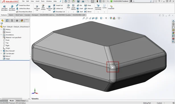
Figure 1: Shown is a complicated corner that connects 4 edges of component with a single radius fillet. As pictured, the fillet feature was able to solve the corner but with less than ideal results.
Figure 1 demonstrates the topic, but doesn’t describe why it’s an ugly fillet. Fillets create tangencies between the faces they connect. This means that as more faces are created by the fillet, there are more directional changes of the parts curvature. Less directional changes result in a smoother, more aesthetically pleasing part. SOLIDWORKS has a few tools to determine how smooth your part is. One of my favorite tools to analyze a fillet is “Zebra Stripes” tool found on the Evaluate tab. Zebra Stripes show direction changes in a face, or face transitions that are undetectable with the standard display of the model. With the Zebra Stripes tool enabled, the goal is to obtain continuous flowing stripes. Misaligned stripes and hard directional changes of strips indicate a bad transition.
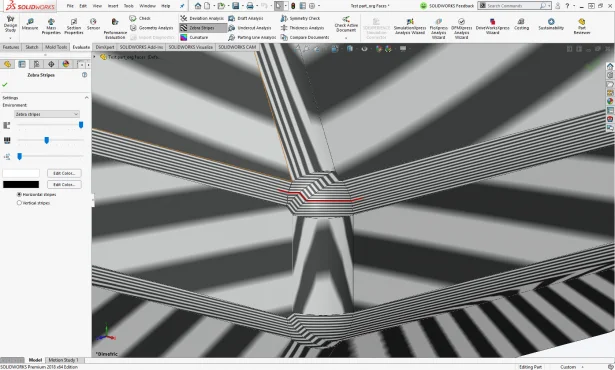
Figure 2: Zebra Stripes analysis around the fillet. The red line is a demonstration of the directional changes across the fillet, which would result in noticeable transitions between the faces.
Reading these stripes can be a helpful guide to understanding the continuity of your model’s faces. Lines that stop at a seam between faces means that the faces have contact, but that is all. If the line continues but changes direction over a seam (like most of the lines shown above), that indicates we have tangency between those faces. If the line continues over a transition as if the transition was not there at all, that means that we have a contour continuous transition. Your continuity requirements may vary depending on the material, surface finish, manufacturing process, or even industry.
If the part above goes through a rendering program such as SOLIDWORKS Visualize these faces will stick out like a sore thumb and reduce the quality of your rendering.
Notice the rendering below. Compare the directional changes in the zebra stripes above, to how the reflected image appears on the fillet. Let’s move on to how to fix fillets like these.

Figure 2.1: Rendered representation of fillet tangencies.
Delete Faces with Fill Option
We’ve discussed, at length, the problem with these fillets and the impact it may have on the aesthetics of your part… but how can you fix them? Manually manipulating faces of a model is a common practice when applying surface modeling techniques. Conveniently, some surface modeling tools are available and useful for
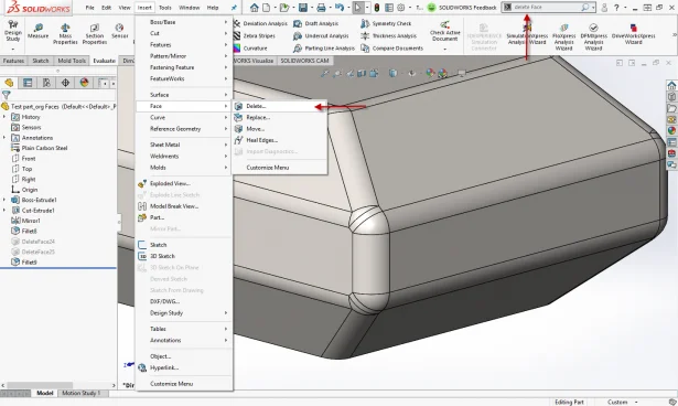
Figure 3: Two default ways to locate the Delete Face tool
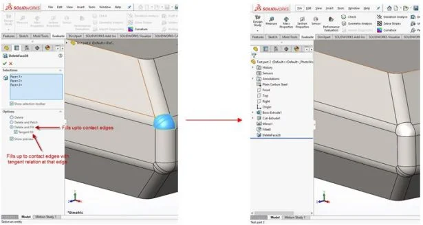
Figure 3.1: Visual description of the Delete Face tool, and how it affects the selected faces
Replacing those three fillet faces instantly makes the corner look better, but would it make a rendering look better? Double check the zebra stripes analysis! We are able to see if this face replacement had any effect on the curvature of these face transitions.
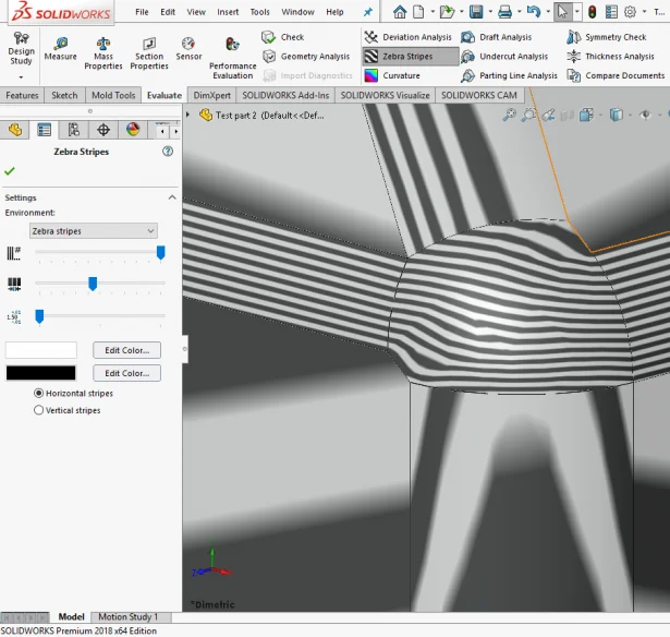
Figure 3.2: The transition between the fillet corner and its four edges. Focusing on the horizontal transition shows significant improvement on how smooth the zebra stripes contour the filleted face.
Rendering a reflection on that filleted face now accurately represents how this polished corner would look. Note that we can still see the edges where fillets start and end. If we wanted to clean this model up further, we could advance to curvature continuous fillets and fills! Though these techniques can be used on any type of face, the application above is used to show why you may want to take pride in how your fillets are represented. It allows us to bridge the gap from functional models to functional and good looking products! Be proud of what you create, and be confident that your parts look good.
