

After teaching 1000’s of students and writing about SOLIDWORKS and SOLIDWORKS Simulation, David Planchard, retired professor WPI, is exploring Design Study, Optimization Analysis and Generative Design. Through this lesson series, David helps educators and their students understand iterative processes through simple examples and industry practices.
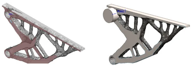
In Lesson 1 and Lesson 2, we focused on applying a Design Study and Topology Study using the SOLIDWORKS desktop environment for an Additive Manufacturing process. In Lesson 3, we saved the part and opened the Solid body and Mesh model in SOLIDWORKS.
In Lesson 4, we will investigate a few Mesh modeling tools in SOLIDWORKS.
What can you do with the existing Mesh model? We can directly export the mesh model to an STL (*.stl) file, Additive Manufacturing file (*.amf) or a 3D Manufacturing Format file (*.3mf). From there, we can address the Additive Manufacturing process.
However, conventional mesh models cannot be scaled or edited. Material cannot be applied and the model has no mass.
We will explore a few tools in SOLIDWORKS to create a Mesh Body from the Mesh model. The tools deliver the ability to scale, add material, and to create faces and surfaces to mate to other components in SOLIDWORKS.
In this lesson, open an existing Mesh part created in Lesson 3. Apply material. View the part Properties. Apply the Surface From Mesh tool. Create a selectable surface on the top inside support cylinder. Apply a geometric reference axis. The reference axis can be used to create a concentric mate inside of an assembly. Next, create a Planar Surface on the mesh body. Create a reference plane. Use the reference plane with a Width mate or a Coincident mate in an assembly. Create a Boss Extrude on the reference plane with an Up To Surface End Condition on the Mesh Body.
Start SOLIDWORKS and Open the Lesson 3 Part
Start a SOLIDWORKS session from your desktop.
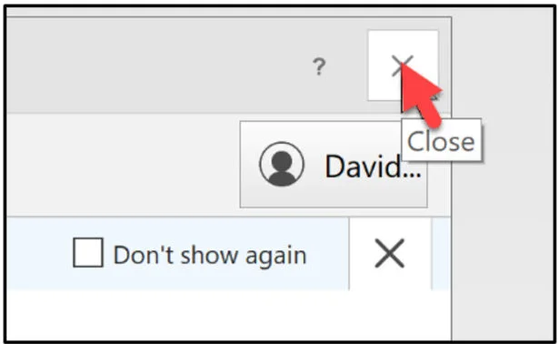
Double-click the SOLIDWORKS 2025 icon. The Welcome – SOLIDWORKS dialog box is displayed.
Close the Welcome dialog box.
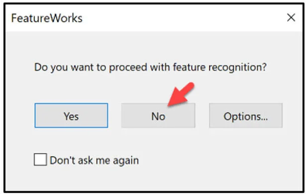
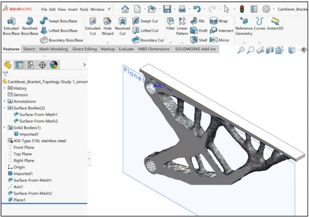
Open the SOLIDWORKS Cantilever_Bracket_Topology Study 1_smoothed_mesh_body part your created in Lesson 3..
Click No as illustrated.
View the Part FeatureManager.
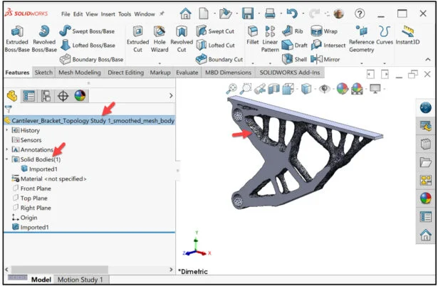
The part is opened as a Mesh body. Because it is a Mesh body, you can add material, and create faces and surfaces to mate to other components in SOLIDWORKS.
Add Material
Add material to the Mesh body.
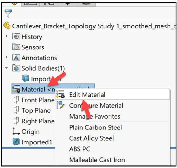
Right-click Material in the Part FeatureManager.
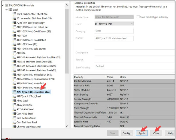
Click Edit Material. The Material dialog box is displayed.
In this example, we selected 316L stainless steel. Click Apply. Click Close from the Material dialog box.
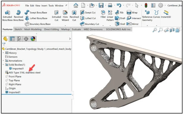
The material is added to the Part FeatureManager. Now you can view the mass properties of the Mesh body.
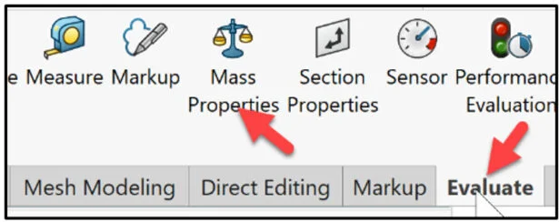
Click the Evaluate tab in the CommandManager.
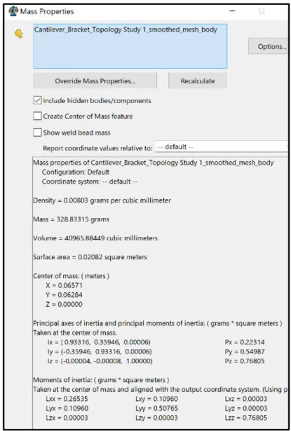
Click the Mass Properties tool. The Mass Properties dialog box is displayed.
View the provided information. Close the Mass Properties dialog box.
Surface From Mesh
How do I put this Mesh part into an assembly? Use the Surface From Mesh tool. Create a center Axis in the top Cylindrical Surface.
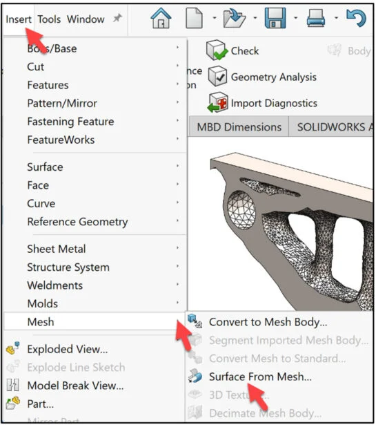
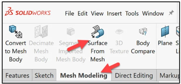
Click Insert, Mesh, Surface From Mesh from the Main menu. Note: You can select the Surface From Mesh command directly from the Mesh Modeling toolbar in the CommandManager.
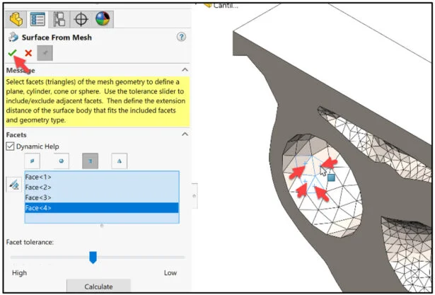
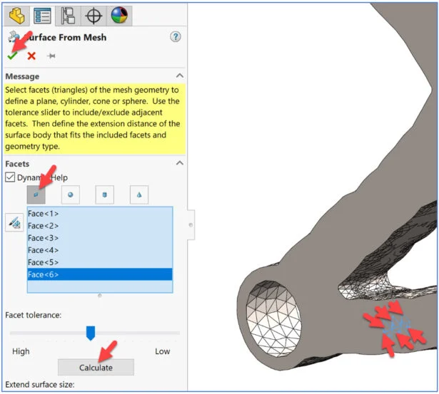
The Surface From Mesh PropertyManager is displayed. Select 4 facets of the mesh geometry to define a cylinder. The tool works best on mesh files with regular prismatic geometry such as planes, cylinders, cones, and spheres.
Select the Cylindrical Surface icon.
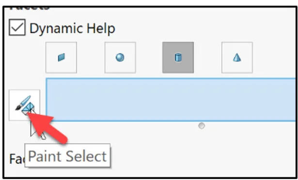
Note: We will not use the Paint Select tool in the lesson. If the faceted model contains facets that do not precisely represent planar, cylindrical, conical or spherical surfaces (commonly derived from scan geometry or sculpting software) it is recommended that you use the Paint Select tool to select many facets from different regions of the group of facets.
Zoom in on the top cylindrical surface.
Select four facets in the cylindrical surface as illustrated. Click OK from the Surface From Mesh PropertyManager.
The Surface-From-Mesh1 is displayed in the Part FeatureManager.
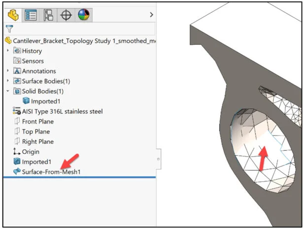
Create Reference geometry. Create a center Axis for the Cylinder.
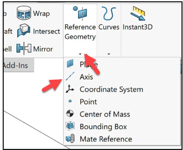
Click the Features tab in the CommandManager. Click the drop-down arrow from Reference Geometry. Select Axis.
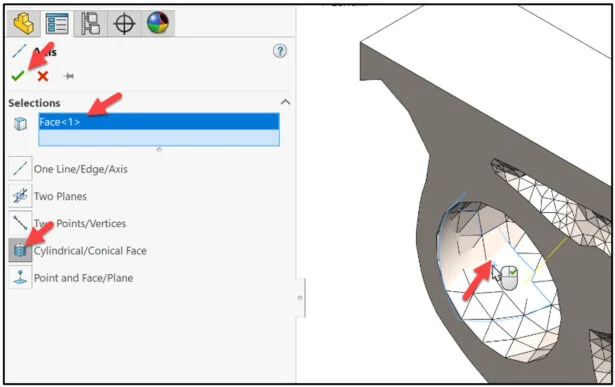
The Axis PropertyManager is displayed.
Click the Cylindrical/Conical Face icon.
Click Surface-From-Mesh1 as illustrated. Click OK from the Axis PropertyManager.
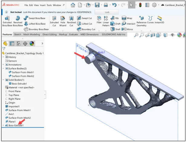
Axis1 is displayed in the FeatureManager and in the Graphics area.
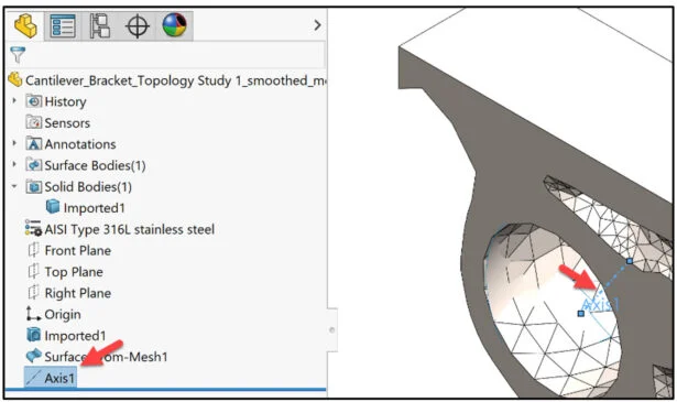
With Axis1 created, we can use this reference for a Concentric mate inside an assembly.
Next, create a Planar Surface on the mesh body.
Click Mesh Modeling from the CommandManager. Click Surface from Mesh.
Select the Planar Surface icon. Create a planar surface by selecting facets that represent the plane. Use the facet tolerance to include or exclude adjacent facets in the definition of the planar surface.
Select approximately six facets as illustrated. Click the Calculate button. View the results.
Click OK from the Surface From Mesh PropertyManager.
Insert Plane and Extrude Features
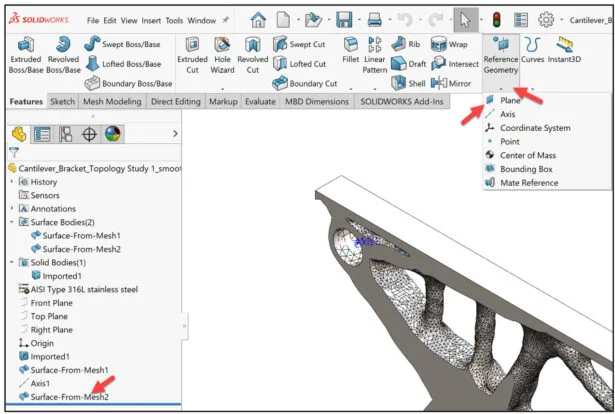
Create a reference plane from Surface-From-Mesh2.
Click Plane from the Reference Geometry drop-down menu.
The Plane PropertyManager is displayed. Click Surface-From-Mesh2. Accept the defaults.
Click OK from the Plane PropertyManager.
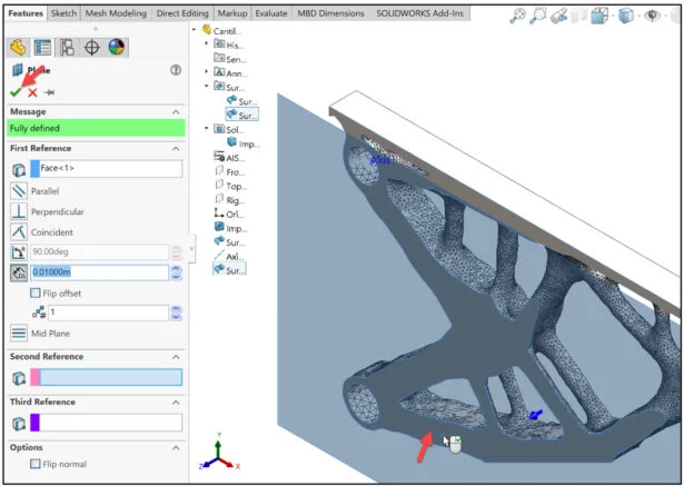
Plane1 is displayed. Use the Plane1 reference geometry with a Width mate or a Coincident mate in an assembly.
Create a Boss Extrude on the reference plane with an Up To Surface End Condition on the Mesh Body.
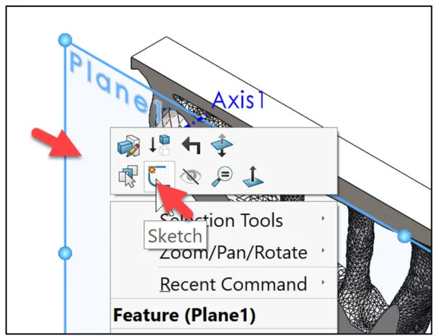
Right-click Plane1 in the Graphics area.
Click Sketch from the Pop-up menu.
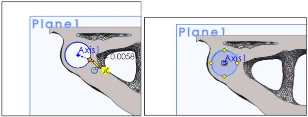
Sketch a circle Concentric with Axis1 as illustrated.
Click Extrude Boss/Base from the Features tab in the CommandManager.
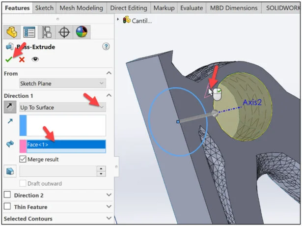
The Extruded Boss/Base FeatureManager is displayed.
Select Up To Surface for End Condition.
Click Reverse Direction. Rotate the model to view the back face.
Click the back face as illustrated.
Click OK from the Boss-Extrude PropertyManager.
View the results.
The lesson is finished.
In Lesson 5, we will open a model in the SOLIDWORKS xDesign App on the 3DEXPERIENCE Platform from SOLIDWORKS. Using Design Guidance, we will define the restraints, apply a load, add material, identify contributing obstacles and analyze the results.
Become a SWUGN Member
SOLIDWORKS and SOLIDWORKS Simulation Educators, register to be part of the SOLIDWORKS User Group Network (SWUGN) with virtual and in person meetings for ever thing about SOLIDWORKS and more.
Additional Resources for Educators and Students – MySolidWorks
You can find additional lessons and learning paths about SOLIDWORKS and SOLIDWORKS Simulation at My.SOLIDWORKS.com.
Design well, Marie