
If you are taking a course in Stress Analysis, you will encounter problems that require you to calculate deflections that occur when certain forces/moments/loads are applied.
You can use Solidworks Simulation to verify your answers. You have the options to choose materials, connections, fixtures and external loads. For each of these options there is a detailed description of how it is used – the advisor.
HOW?
First you have to create the part/assembly that you are going to use. You can choose the materials now, or leave that for later, in the simulation.
Start a New Study from the Simulation Add-In. Here, you can choose the materials you are interested in, from the Solidworks Database.
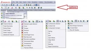
Afterwards, you can select fixtures, such as rollers, sliders or elastic supports. In this example, I am using fixed hinges at each of the rods on the left.

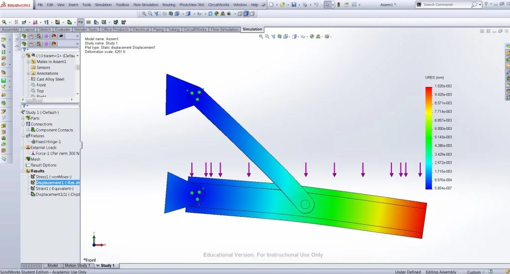
Then you can choose the external loads – forces, torques, pressures – and you also have the options of adding gravity, centrifugal forces or distributed mass. I have used a uniform load on the top face of the I-beam.
Before running the simulation, you can specify the different types of connections in your assembly. These include: bolt, pin, spring, bearing etc.
Now it is time to run the simulation.
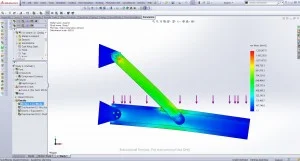
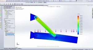
Mousing over the parts in the assembly will show the initial positions/shapes of the components. You can also click on the “Deformed Result” button (found to the right of “Run” and “Result Advisor” buttons) to alternate between the initial and deformed views.
The legend can be used to check the answers you calculated for your problem.
Model and Analysis Files:Applying external loads – uniform distribution
I hope this was helpful,
Ruxi
—
Ruxandra Duca
Aerospace Engineering ’16
Worcester Polytechnic Institute