
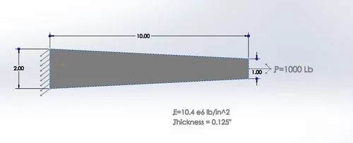
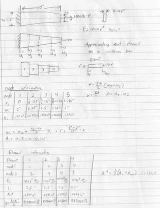
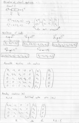
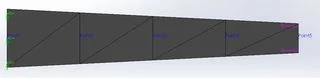
One class I am taking this year is a class on the finite element method (FEM). I decided for this post to solve out a relatively simple FEM problem by hand and then compare my answer by using SolidWorks Simulation. The picture above describes the problem. There is a non-uniform beam that has a force pulling axially on the end of the beam. Below are my hand calculations to solve this problem. I broke the beam into 4 elements and treated each one as a uniform beam of different height.
In SolidWorks, I created the shape of the beam to the dimensions of the problem. For the material I created a new custom material that had the modulus of elasticity of 10.4e6 lb/in^2 and then I choose the Poisson’s Ratio to be 0.3 and choose a density of 0.1 lb/in^3 which is of similar density to aluminum. After the material was applied I added five sensors along a center line of the part. These sensors were simulation type sensors set to workflow sensitive. These were placed in the model to get the displacement at the same points I found with my hand calculations. I then went under tools, add-ins, and selected SolidWorks Simulation. I created a new static study and check the box for 2D simplification. This opened a window where I chose the section plane and the thickness of the part. From here I fixed one side of the part and added a force of 1000 lbs on the other side.
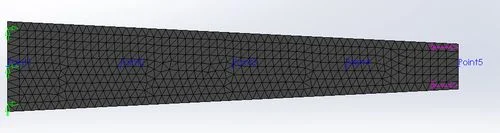
When I meshed my model I created a very course mesh with only 8 elements which can be seen below. This was done by setting the global size of the mesh to 3 inches and tolerance to 0.15 inches. I did this to have a similar number of elements to compare to my hand calculations.
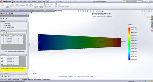
I then ran the calculation. I displayed the displacement plot and then used the probe tool to get the results of my sensors. The sensors are numbered from left to right and correspond to the subscripts in my hand calculations as well. Below you can see the results I obtained for the course mesh as well the answers I got through my hand calculations.
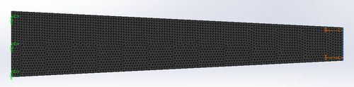
I created two more studies, one of medium mesh and one of a fine mesh to test for convergence. Below are the meshes and their results which are directly below them.
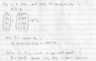
I also found the reaction force at the fixed end by going under the results advisor and selecting list results force. I then chose the edge that was fixed and clicked update. This showed that the resultant force was 1000 lbs in the negative x direction which is pretty close to what I got with my hand calculations and is what the force should be. This is because there is only one force of 1000 lbs in the positive x direction so there would need to be an equal and opposite force at the fixed end of the part.
I hope you enjoyed this and feel free to solve this problem by hand or by using SolidWorks Simulation.
Ian Jutras
Worcester Polytechnic Institute
Mechanical Engineering 2013