
About two week ago I was wondering if it was possible to make a coordinate system that was based off of the location of the center of mass. I figured that this would be useful so that it would be possible to place a part in an assembly with respect to its center of mass. This would allow that part to be perfectly balanced on another part or assembly thus creating more stability in the assembly if it were to be made. This is just one of the benefits that I saw from being able to locate a coordinate system there. At the time I was pretty sure that it could not be done as there was no way from the mass properties to set the center of mass as a coordinate system. However, the other day I was playing around in SolidWorks and that same thought came to me so I decided to investigate it further. After searching through most of the SolidWorks menus and attempting this in as many ways as possible I finally figured it out. This is how to make a coordinate system based on the center of mass of a part in SolidWorks 2011.
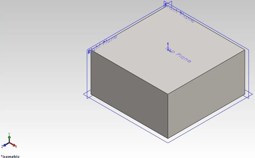
- I first created a rectangular block which will represent my part that I want the coordinate system in. This was created in the positive section of the coordinate system
- The next step is to create equations.
- Under Tools click equations
- Click Add and type “CenterMassX =” (this will be the center of mass in the x direction)
- Then click the downward pointed arrows at the bottom right of the screen
- From there scroll down and select SW-CenterofMassX
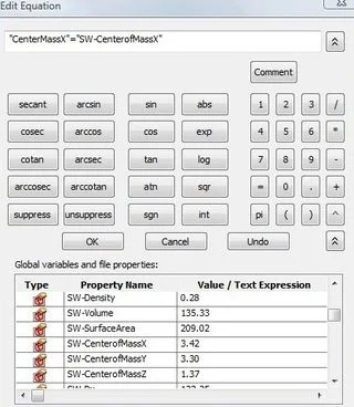
- Then click ok. This just set a variable that is equal to the center of mass in the x direction
- Repeat this for the center of mass in the y and z direction making sure to define them so you know which direction is which
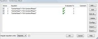
- Now you should have 3 equations like mine shown below
10. The next step is to create reference lines for where the new coordinate system will be
11. A line was drawn on the front plane in the positive x direction.
12. Using Smart dimension, dimension the length of this line
13. When the modify box pops up click the down arrow on the left side of the box
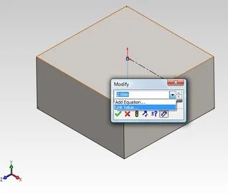
14. Select link value and under the name drop down select your variable for the center of mass in the x direction.
15. This dimension is now linked to that of the dimension for the center of mass in the x direction
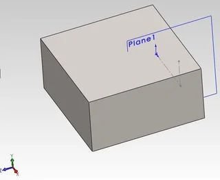
16. Next a plane was inserted on that line using the point not on the origin and the line itself as the references.
17. A line was drawn on that plane in the positive y direction.
18. Dimension this line the same way as was done in steps 12-14 but this time select the variable for the center of mass in the y direction
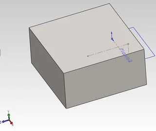
19. Another plane was inserted on that free end
20. Finally a line was drawn on that plane in the positive z direction.
21. Dimension this line the same way as was done in steps 12-14 but this time select the variable for the center of mass in the z direction
Note: What has just been created was a line in the direction of each axis of the coordinate system. I tried doing this in a 3D sketch but it had problems when it came to having a center of mass that had a negative direction with respect to the origin.
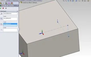
22. At this point we now have a point that we can create a new coordinate system
23. Under the features tab click reference geometry and then select coordinate system
24. For the origin select the point that is the free end of the line that was just created.
25. Select the line that we drew in the positive x direction for the x axis and the line drawn in the positive y direction for the y axis.
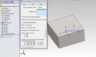
26. That is all that is needed to create the coordinate system
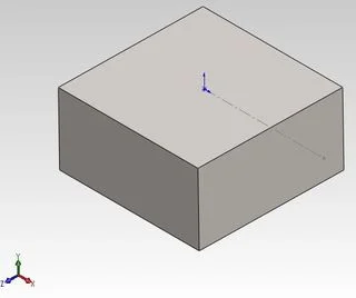
27. Now you have a coordinate system based on where the center of mass is which is seen below
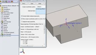
28. If you add another feature such as a boss extrude to the original block and rebuild the part, that new coordinate system will then update.
29. To verify that it is indeed the center of mass just go to the evaluate tab and then click the mass properties option.
30. A pink origin should show up at exactly the same spot as your new coordinate system, see modified part below
The method that was just explained can be used on any part and it does not have to be inserted at the end of all the features. As long as the part is rebuilt it will update accordingly. Sometimes the document may need to be rebuilt again depending on if the new axis updated. Try making a part and inserting it in an assembly and use that coordinate system as a reference when mating that part. You can download my model that I used below. I hope you enjoy
Ian Jutras
Worcester Polytechnic Institute
Mechanical Engineering 2013