
If you haven’t tried your hand at 3D Sculptor, you’re in luck. Thanks to Jordan Tadić, Senior Solution Consultant, Dassault Systèmes SOLIDWORKS, who shared this great video on how to create an artificial hand using 3D Sculptor.
3D Sculptor is a browser-based role for subdivision (Sub-D) modeling that runs on the 3DEXPERIENCE platform enabling designers to easily craft complex shapes using a push and pull interaction.
Whether you want to create an artificial hand for your Halloween props or contribute to a greater cause like Tadić, who was involved in the 3DEXPERIENCE for Good hackathon and tasked to redesign the LN-4 prosthetic hand for the LN4 Hand Project. The LN4 Hand Project is sponsored by Ellen Meadows Foundation and has distributed more than 50,0000 prosthetic hands in more than 80 countries through volunteers that have designed them.
This blog will cover Tadić’s favorite features and offer some tips and tricks for creating an artificial hand with 3D Sculptor. Watch the full video at the end of the blog.
Wondering where to start? It’s like working with a digital hunk of clay so you can really play with it and mold the clay into any shape imaginable.
Getting started and scaling the shape
When starting on a design he suggested using the most versatile shape tools, the Box and Quad Ball tools. “There’s no shape you won’t be able to make with one of those two,” said Tadić.
In this case he went with the Box command to create the first finger. You can also use the Bounding Box straight from the Box command to enter new values for the size of the box to scale the subdivision geometry uniformly or non-uniformly.
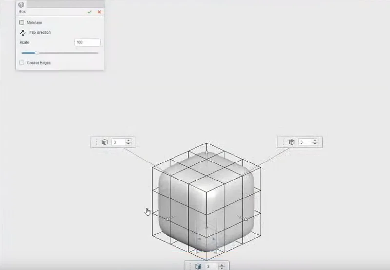
Then you can shape your model to the approximate size using a push-pull interaction. With 3D Sculptor you can easily push and pull faces, edges, and vertices to adjust the shape in real time.
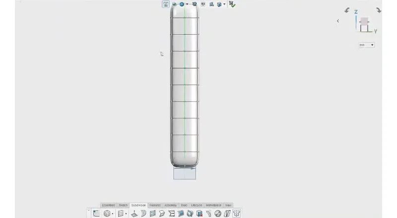
The next thing you need to figure out is how many subdivisions you have on the model. You’ll see a vertical line going down the model that represents the columns of faces that you want on that side of the model. You can place a line where the symmetry line is going to be and that’s just going to make the model update a lot more predictably when you do that.
You can use the Scale command to resize the shape of the subdivision feature.
The side of the finger doesn’t need to be symmetric, so he chose one column of faces to get a nice round radius on the side. For the length he entered 10 for the dimension, which he said you don’t have to get right on the first try because you can always insert loops or delete loops after if you’ve created too many. He said he relates this process to sketching splines in SOLIDWORKS where you don’t want too many points, which would make it too much to control. On the other hand, you don’t want too few either because you need a good level of detail.
Adding symmetry
Tadić pointed out that one of the best things about the 3D Sculptor interface is that the context toolbar always pops up just like how it does in SOLIDWORKS user interface. The context toolbar pops up to recommend the next step you might consider based on what you selected.
Next when you select a plane you’ll be asked if you want to make it symmetrical. And in this case, you do so when you say yes 3D Sculptor will automatically choose that plane and start up the Symmetry command.
By turning on Symmetry, any edit or manipulation you perform on the subdivision surface will be mirrored to the other side, ensuring that your design is symmetric and accurate.
Trying to keep a subdivision design symmetric without such a function would be pretty much impossible. And being able to create symmetry, only when you need it, allows you to create geometry where some areas are symmetric, and some are not.
Scaling entities
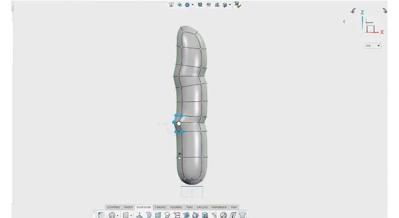
Next Tadić needed to “scrunch” down the wrinkled sections of the finger on his model. He said when doing so to pay attention to the robot manipulator on the screen that will center itself around what is selected. In this case he had to make the wrinkles one at a time and then scale them down individually.
You can also select an entire loop of entities by double-clicking an edge. “Don’t you wish you could do that in SOLIDWORKS,” he commented. The good news is 3D Sculptor and SOLIDWORKS work together seamlessly.
Proceeding with the model he continued to double-click the edges to translate the wrinkles and make it look more accurate, however the knuckles were looking awkward and had sharp edges. To fix those you can easily “window select” them and scale the section outward to soften the radius.
Adding creased edges and detail
At this point he had what looks like somewhat of a deformed hot dog and needed to make it look more realistic. But first he needed to make the bottom of the finger flat so he could integrate it with the rest of the design easily. To do this he selected the Creased Edges command. Then he used the Align Guide Line command to taper it inwards. He noted to be careful that doing this from the side view can ruin the wrinkles he added earlier so he used the Flex command to give it a tapered effect. He said he would actually call it the “taper” tool instead of Flex as that is what you are pretty much doing.
The Flex command is a great function for creating controlled “fall off” geometry. Itprovides a manipulator to control the amount of fall-off and the distance over which the fall-off acts. As you pull the manipulator handle away from your control line, the geometry will follow proportionally.
Alignment and numerical input
To ensure faces are perfectly aligned you can use the Align to Geometry command. Just select a plane and from Context tool bar select Align to Geometry.
To check the size of your model you can turn on the Bounding Box command which shows the live measurement of the total height, depth and width of the model. And you can tweak the model and the measurements will update live. Even better than that when you click on the context tool bar to activate the Scale command you can scale the subdivision geometry uniformly or non-uniformly.
For the hackathon project Tadić and his team had to figure out what the average size was across all the genders and all the age group and used that as the baseline for entering the numerical data in the Scale command. He noted to be sure to turn off symmetry when entering numeric values.
He then pulled up the palm of the model he had previously created and realized the fingers were in the wrong location and he had to move the whole thing. Using the keyboard shortcut “Control A” he was able to select the entire geometry and translate all the points at once.
Another pointer he gave is to hide the tangent edges to get a more realistic view of the model at any time.
Ordered Geometrical Sets
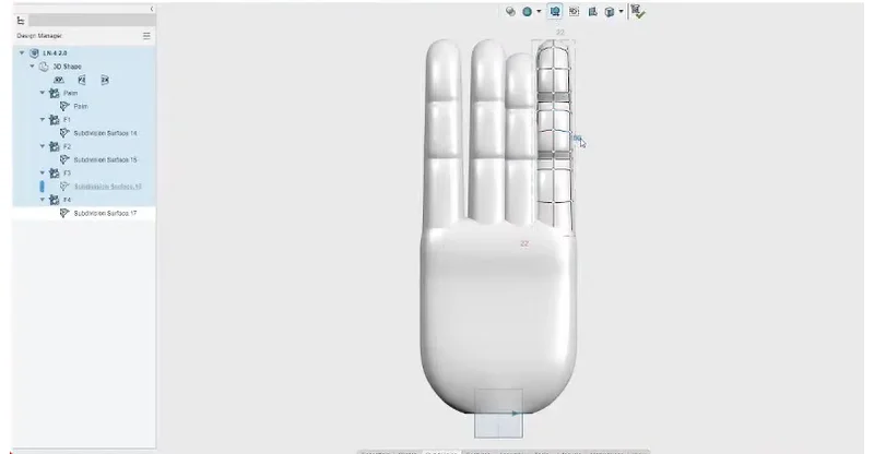
To create the other four fingers, he used the Ordered Geometrical Sets command to add to the palm of the hand.
He said to think of it like creating folders. So, what he did here was create a separate OGS for each finger to keep the subdivisional surfaces separated in those OGS’s for organizational purposes. Then he took the first finger he created and copied and pasted it within the other OGS’s.
You can copy and duplicate sub-division features as much as you want and tweak them each time as well. He then pasted one ordered geometrical set into the second ordered geometrical set and centered it on the palm using the Center On command to get it perfectly centered.
You can copy and duplicate files as much as you want and tweak them each time as well. He then pasted one ordered geometrical set into the second ordered geometrical set and centered it on the palm using the Center On command to get it perfectly centered.
Next, he used what he called the most fun tool in 3D Sculptor, the Arc Bend to bend the entities. Since a hand is not completely flat you can grab the arc to bend the entities around it in the model.

Watch the video to see the process in action from about 10 mins to 30 mins in and watch the full video for more examples of how 3D Sculptor was used.
To learn more about 3D Sculptor and other 3DEXPERIENCE Works roles see the SOLIDWORKS Cloud Offer.
To see what’s new in the browser-based design and engineering roles, including 3D Sculptor check out these blogs:
The July 2022 Update is Here – What’s Hot in the SOLIDWORKS Browser-based Design Roles
What’s New 3DEXPERIENCE Works Design 2022: February Update