
In my opinion, one of the most underutilized tools in SolidWorks Simulation is the Design Study. Design studies allow you to easily set up a number of ‘what if’ scenarios and run them all with the click of a button. Sure, it might take a couple extra minutes to set up a few parameters, but the extra setup time will pay off handsomely later.
Let’s take a look at the effects of varying mesh size for a stress concentration. The first step is to create and run a Simulation Study to verify the model setup and boundary conditions. Second, set up a parameter for the global element size. Third, create a design study, using that parameter as a variable. Finally, add a constraint; in this case we’ll use the maximum stress from the Simulation study we previously created. When these steps are complete, run the design study and all of the scenarios with the click of a button!
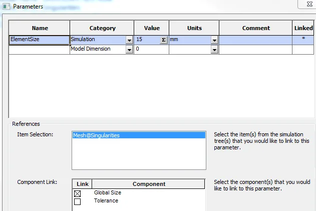
Setting up a Parameter can be done in two ways. From the Evaluation tab of your Command Manager, you can left-click the down arrow on the Design Study icon and choose ‘Parameters’. Alternately, from your Simulation feature tree, you can right-click on “Parameters” and choose ‘Edit/Define…’. The keys to creating a Parameter are to provide a name, choose the appropriate category, then link that parameter to the item you want to vary in the design study. In this example, I want to link the Parameter to ‘Global Element’ size, so I’ll click on the Mesh icon from my Simulation study feature tree.

The next step is to insert a Design Study into your model. Use the down-arrows to add the Element Size variable to the Design Study. In the second column, I chose to use discrete values for element size. These can be typed in using a comma to separate values. In the Constraints section, use the pull-down menu to add a Simulation Data Sensor to the model, specifically to monitor the maximum stress. Be sure to choose the Simulation study you want the sensor to reference for data. Then un-check the ‘Optimization’ box and click ‘Run’.
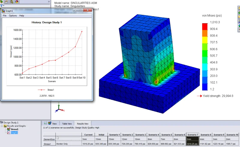
When the Design Study is finished running all of the scenarios, you will have a plot for each constraint utilized. In the picture below, the stress plot from one of the scenarios is shown. I’ve also added a ‘Local Trend Graph‘ to show the stress concentration model does, indeed, show a diverging solution with regards to stress.
I could have arrived at the same information in a couple of ways not utilizing a Design Study. The most common method I encounter is a user creating ten Simulation studies, then manually meshing each with a different Global Element size. That is, quite simply, a waste of time! The extra few minutes spent creating Parameters and properly defining a Design Study can be done much faster than creating several individual studies. I’m certain with a little investigation you can find plenty of uses for this powerful tool. Now go make your products better with SolidWorks Simulation!
Want to learn more about SolidWorks Simulation? Check out our First Look at Simulation video to see how simulation could improve your own designs and reduce prototypes.
***
Bill Reuss is a CAE Specialist at 3DVision Technologies, a SolidWorks Value Added Reseller with locations across Ohio, Indiana, and Kentucky. He is a regular contributor to 3DVision Technologies’ Blog where you will find new ideas to improve your productivity with SolidWorks Simulation.