
Ever wondered what it would be like to be mentored one-on-one by a senior engineer that’s using SOLIDWORKS to successfully deliver solutions to industry clients? My name is Rafael Testai, and in this video series “Mechanisms & Mentorship,” we’ll take a look behind the scenes to see how a hand-picked engineer has designed one of their mechanisms in granular detail. We’ll “open the hood” to analyze their CAD design and thought process behind the solution. I’ll ask them questions about the project, roadblocks, challenges, specific insights they learned, and how they’re using SOLIDWORKS to solve real world problems.
You’ll learn a mixture of soft skills and hard skills. This series is perfect for viewers who are already proficient in SOLIDWORKS (CSWA, CSWP, CSWE) and want to take the next step in their careers.
In this episode of Mechanisms & Mentorship, I’ll interview Mechanical Engineer & LabView Programmer, Ben Sandoval from TeamPipeline.us in Arizona. We’ll focus on the two clever fixtures he designed to take a repeatable non-contact measurement on medical devices, and a method to measure the frictional forces induced while inserting shafts through non-linear pathways. The video starts off a bit technical. Hence, if you’re having trouble following the verbal explanations, feel free to fast forward to min 20:30, where we’ll show pictures, videos, and mechanisms to support & compliment these statements later in the episode.

Time Stamps:
1) What Problems Were You Trying to Solve? (Min 0:25)
Problem #1: Develop a fixture that enables non-contact measurement on a suspended device shaft. Problem #2: Develop a machine to measure the frictional forces while traversing non-linear geometries. Problem #3: Design, procure, assemble, program, validate, and deliver both fixtures within the time window.
2) How Does a Senior Mechanical Designer Approach a Problem? (Min 4:45)
• First, it is necessary to gather as much information about the problem as possible through multiple meetings with the customer. We keep detailed notes and documentation to ensure that our completed systems perform up to customer expectations. Then, we step back and quantitatively define what we’re trying to accomplish and how it is different from owned by the customer and those readily available off the shelf – this opens a lot of insight into customer expectations and operational capability.
• What parts of the system can be purchased off the shelf? Are there components of the System that can only be purchased off the shelf?
• How does the customer want the test system packaged – Environmental conditions? Sensors/Systems/Controls/Automation Level and UI, Repeatability, Accuracy and Traceability; Test Conditions? User Interaction and Safety Constraints.
3) Researching Existing State-of-the-Art Technologies
“State-of -the-Art” can loosely be described as ‘the most modern technologies and processes in that specific area of innovation.’ Ben researched state-of-the-art currently used to perform these inspections to begin understanding how to solve the problem. Specifically, he looked at the interventional device testing equipment (IDTE) from MSI for insights and inspiration. (See image below) (Min 16:11)
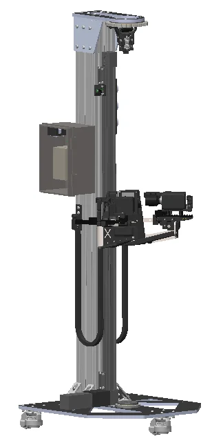
4) The Solution: CAD of the 2 Assemblies (Min 20:15)
For taking non-contact measurements, Ben uses a 1200mm linear actuator, 2x 50mm actuators tied to micron precision digital gauges, 2x HDMI screens, and 2x 4K high speed smart cameras. This allows the operator to take accurate measurements at any point along the shaft. I highly recommend you watch the details of his explanation on the video.
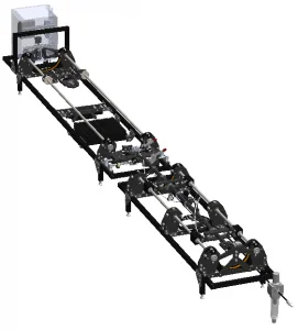
5) Mechanism to Clamp Small Shafts/Cables (Min 28:00)
For measuring induced friction, Ben used a two-part fixture. The first half contains a carriage mounted on linear rods and a belt-based clamping drive system. When the two sides clamp together, they squeeze the shaft with the rubber belt allowing high gripping forces without damaging shaft materials or surface finish. The second half is made up of a carriage floating on air bearings that translate the induced friction into lbsF read by a force sensor at the far end.
If you read until the very end, I greatly appreciate it. I would encourage you to follow me on Linkedin so that we can stay in touch and you can be notified when more articles like this one get published. I lead with value and my writing style is direct and to the point.
? https://www.linkedin.com/in/testai/
Any recommendations on who you think I should interview next? Feel free to reach out to me on Linkedin or Instagram. I read all correspondence.
Linkedin: https://www.linkedin.com/in/testai/
Instagram: https://www.instagram.com/rafael_testai/