

Hello to all,
Welcome to the new edition of the SOLIDWORKS Support Monthly News! This monthly news blog is co-authored by members of the SOLIDWORKS Technical Support teams worldwide.
SOLIDWORKS Detailing Mode
By Bishwaraj Roy
SOLIDWORKS Detailing mode helps to enhance productivity by letting users to open complex drawings consisting of large assemblies, many views with lots of sheets and annotations very quickly, which are otherwise very much resource consuming.
Detailing Mode allows a user to load a drawing without having to load the referenced components. The model does not get loaded but the drawing views are intact, so there is no loss of detail.
How to open a drawing in “Detailing mode”?
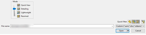
Drawings can be opened in Detailing mode from the “File” menu and navigating to “Open” and then when selecting the drawing, “Detailing” mode is available.
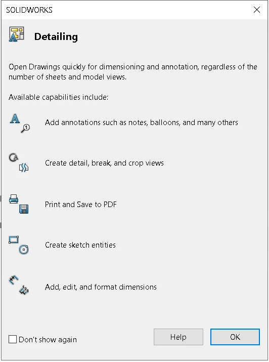
After selecting open, SOLIDWORKS shows what operations can be done in Detailing mode:
When a drawing is opened in detailing mode, you can see the note “detailing mode” appear next to the drawing and sheet name like below:

How is “Detailing” mode different from “Detached drawings”?
- Detailing mode is similar to detached drawings, but different because a drawing does not need to be first saved in detailing mode like detached drawing.
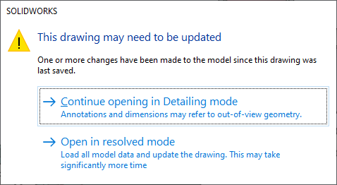
- Detailing mode has the advantage that when any referenced components have changed, and while opening the drawing, a dialog box will pop up which warns user that the drawing needs to be updated and user can continue opening in detailing mode or resolve all the model data and update the drawing.
What are the capabilities which we can do in Detailing mode?
Some of the capabilities of working on drawings with “Detailing” mode are:
- Notes, including notes with leaders
- Weld callouts
- Linear and circular note patterns
- Geometric tolerances
- Surface finish symbols
- Datum feature symbols
- Datum target symbols
- Revision symbols
- Revision clouds
- Radial and linear dimensions, including use of the Smart Dimension tool
- Locations labels
- Balloons
- Ordinate dimensions
- Magnetic lines
- Angular running dimensions
- Change the position, rotation, and labels of drawing views.
- Copy or cut drawing views and paste them onto the same or other sheets within the same drawing.
- Within annotations, add links to the displayed values of dimensions and other linkable annotations.
- Insert sketch blocks.
- Add general and revision tables.
- Save the file as a PDF/DXF file, or print as a PDF.
With SOLIDWORKS 2021, some major enhancements in detailing mode are:
- We can create Break, crop and Detail views (It is necessary to first save the drawing in SOLIDWORKS 2021)
- Add hole callouts: In Detailing Mode, we can add and edit hole callouts for holes that use Hole Wizard, Advanced Hole, Hole, Extruded Cut, Swept Cut, and Revolved Cut features.
- Editing Existing Dimensions and Annotations in Detailing Mode: In Detailing Mode, for existing dimensions and annotations created in resolved mode, we can edit additional characteristics. It is possible to do the following:
- Edit dimension tolerance values
- Edit dimension characteristics such as line type and arrow type
- Add and remove dimensions in sets of chain and baseline dimensions
- Edit annotation note characteristics and content
Here is a short video showing some of the functionalities in Detailing mode in SOLIDWORKS:

Terminology changes in SOLIDWORKS Simulation 2021
By Julien Boissat and Jay Seaglar
SOLIDWORKS Simulation 2021 introduces a broad range of changes in terminology for contacts and component interaction.
The goal of these changes is to improve clarity and better align the terminology in SOLIDWORKS Simulation with industry standards.
The implementation of the terminology changes will take place gradually over the course of the Beta phase of SOLIDWORKS Simulation 2021 and may benefit from adjustments when necessary.
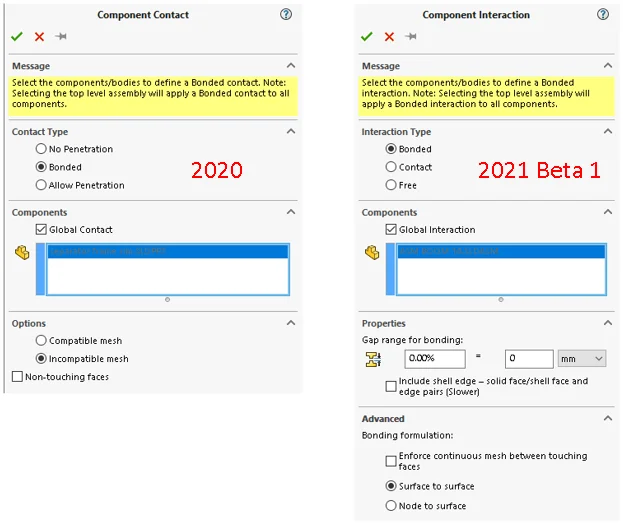
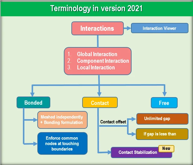
1. Contact ==> Interaction
One of the benefits of the new terminology is to reserve the term Contact (if you’re confused, don’t worry – read on). The new general term for how bodies behave with each other is Interaction. So out goes the expression Bonded contact (an oxymoron), replaced with the clearer Bonded interaction.
This change allows getting rid of the former No Penetration type of Interaction, and simply calling it Contact. Similarly, Free is the new name for Allow Penetration.
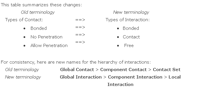
A downstream effect of these changes is the new term Interaction Viewer to replace Contact Visualization Plot.
2. Compatible / Incompatible bonding
The concept of Compatible and Incompatible bonding has been well established in SOLIDWORKS Simulation. It appeared in version 2006, which introduced Global bonding with incompatible mesh for assemblies. Although the terms Compatible and Incompatible were effective in distinguishing between the methods, the words did not describe well the underlying technology. Eventually, these terms remained unique to SOLIDWORKS Simulation, and the rest of the industry did not adopt them.
Furthermore, the trend in the industry has favored Incompatible bonding over Compatible. Reasons for this trend include:
- New technological developments in constraint equations made Incompatible bonding more accurate.
- Meshing coincident bodies to enforce common nodes between touching boundaries (Compatible bonding) is a common cause of mesh failure
- Meshing bodies independently (Incompatible bonding) produces better quality elements.
After 13 years of having Compatible bonding as the default, version 2020 already made the switch to having Incompatible bonding as the default.
Version 2021 completes the transformation started in version 2020. SOLIDWORKS Simulation 2021 seamlessly achieves Bonded interactions after meshing bodies independently using a Bonding formulation of either Surface to surface or Node to surface constraint equations.
Users can still opt for the alternative and choose to boundaries when meshing using the Standard or Curvature Based meshers.
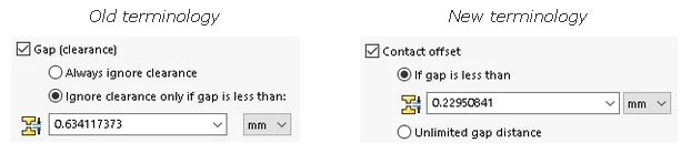
3. Gap (Clearance) ==> Contact Offset
The Gap (Clearance) option takes on the new name Contact Offset in Contact Interactions. This terminology change combines two benefits:
- It is consistent with the terminology in place in SIMULIA.
- It is coherent with the name of the new Contact Stabilization option.
Always ignore clearance takes the new name Unlimited gap distance. With this option, the program enforces the Contact offset irrespective of the gap between the selected entities.
Ignore clearance if gap is less than is shortened to If gap is less than.
4. Other miscellaneous changes
Here is a list of some other changes.
The Show advanced options for contact set definitions (no penetration and shrink fit only) option is ON by default. Therefore, the option to show these settings is now obsolete and has been removed from
The Simplified and More Accurate bonding formulations take more explicit names, respectively . The Bonding formulation and Contact formulation now use consistent terminology.
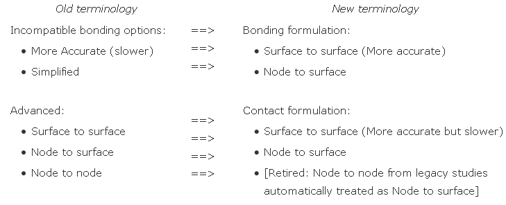
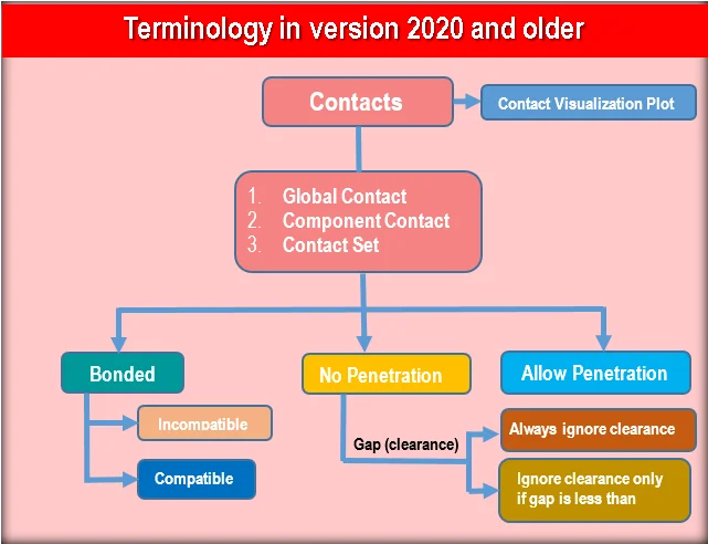
5. Summary and chart
Refer to the following charts for a color-coded, side-by-side comparison of the terminology.
Noteworthy Solutions from the SOLIDWORKS Knowledge Base

When installing the SOLIDWORKS® 2021 SP1 or earlier software, what can cause the error ‘A newer version of this application is already installed’ and how do I resolve this issue? This error appears because of a change in the Visual Basic for Applications (VBA) version 7.1, introduced in the SOLIDWORKS® 2021 SP2 software.. To get more information, see Solution Id: S-078838
When opening a drawing file in the SOLIDWORKS® 2021 application, why are shaded drawing views missing or distorted? There is an issue with some AMD video cards where the new graphics functionality in SOLIDWORKS® affects the display of shaded drawing views in SOLIDWORKS 2021. To get more information, see Solution Id: S-078884

When using SOLIDWORKS® Manage in a high latency environment, are there any recommendations to help improve performance? In general, a network response of over 200 milliseconds leads to performance issues within the SOLIDWORKS® Manage software. To get more information, see Solution Id: S-078834

How does the ‘List Heat Power’ tool work and what are the limitations? The ‘List Heat Power’ and ‘List Heat Energy’ tools first became available with the release of SOLIDWORKS® Simulation 2011. These tools make it possible to determine the heat power generated or dissipated through selected entities accurately for steady state and transient thermal studies.. Please see solution Id: S-078712 for more details.
That’s it for this month. Thanks for reading this edition of SOLIDWORKS Support News. If you need additional help with these issues or any others, please contact your SOLIDWORKS Value Added Reseller.
Comments and suggestions are always welcome. You can enter them below.