Have you ever been interested in SOLIDWORKS Simulation but didn’t know where to start? With such a wide variety of design analysis solutions, Simulation can be an intimidating product for someone newer to the SOLIDWORKS suite of products.
Well we here at Alignex have you covered. Introducing part 1 of our Introduction to SOLIDWORKS Simulation series. Jump right in and discover just how quickly you can incorporate Simulation into your product development workflow today.
Video Transcription
Hi, my name is Sean, and I’m the Simulation Product Specialist here at Alignex. In the upcoming video series, I’m going to be walking you through the basics of setting up and running an FEA study, also known as a simulation.
Traditional FEA software is intricate and difficult to use, reserved only for the most experienced analysts. SOLIDWORKS Simulation is not only simple and intuitive, it can also handle complex simulations with ease.
But as the old saying goes, garbage in, garbage out, so it’s important to understand the basic concepts in order to produce reliable data. These videos will provide a foundational knowledge to those that are new to computer aided engineering and help get you pointed in the right direction to successfully completing your first FEA project.
We’ll be showing you how to:
- Prep your geometry
- Assign materials
- Assign fixtures and loads
- How to mesh the model
- How to interpret the results
SOLIDWORKS Simulation is a virtual testing environment to analyze your design, evaluate its performance and make decisions to improve product quality. But how does it accomplish this? Behind the scenes, the software employs a numerical technique called Finite Element Analysis, or FEA.
The concepts behind FEA were developed in the early 1940’s, but the method became more mainstream in the 1980’s and 90’s when it was implemented on desktop computers. Today, FEA is a powerful tool that is widely used by designers across many industries. It’s used for solving structural, vibrational and thermal problems virtually before they pose a real problem in reality.
Here is a fun fact you might not be aware of. Every seat of SOLIDWORKS CAD includes a free tool called SimulationXpress, which can be used to analyze a single body part with simple loads and supports. You can activate by navigating to the Tools Menu, then Xpress Products.
For additional analysis capabilities, SOLIDWORKS offers three simulation packages designed to meet the needs of different users:
Simulation Standard is used for structural, motion and fatigue analysis of parts and assemblies.
Simulation Professional adds more capabilities including frequency, thermal, buckling, drop test and optimization studies. It also includes a full set of productivity tools that allow you to work faster and achieve greater accuracy in your results.
Finally, the Simulation Premium package is capable of analyzing plastic and rubber components, metal forming operations, composite materials, and dynamic loads such as oscillating or vibrating structures.
Regardless of the specific design being tested, the fundamental steps of any FEA study are always the same.
We start with a geometric model. This could be a native SOLIDWORKS part, multi-body part, or an assembly. It could also be a file from another CAD system, or even a neutral format such as a STEP, IGES, or a Parasolid. SOLIDWORKS Simulation is capable of analyzing all of these file types.
Next, we assign materials to all the components, define the loads acting on the structure and apply restraints to describe how it’s anchored or held in place.
Lastly, we approximate the geometry by splitting it into smaller and simpler entities known as elements. This process is called “meshing”, and it can be automated by the software. For advanced users who would prefer more control over the meshing process, there are built-in tools that allow for additional refinement.
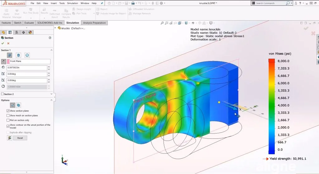
After running the study, we can view the results using a variety of color plots, graphs, animations and reports.
In the upcoming videos, we will explore each step of the FEA process in greater detail.
Editor’s Note: This post was originally published in October 2018 and has been updated for accuracy and comprehensiveness.