

Virtually every one of us during school time, playing any sport in which we used the ball, could hear commands to “curve the ball”, “use your wrist” or “don’t kick with the point of your shoe.” The ball with proper rotation was able to fly wherever we wanted and turned during the flight. Changing the track was associated with how much we “curved” the ball. The phenomenon of force arising as a result of object rotation in the velocity field is called the Magnus Effect. We will introduce this subject today with the help of SOLIDWORKS Flow Simulation.
Description of the phenomenon
The reference to sport is not accidental, because for the first time the given phenomenon was noticed by Sir Isaac Newton during tennis competitions where he was able to correctly determine that the turn of the ball depends on the speed of rotation. However, a full description of the phenomenon and the model was created by Heinrich Gustav Magnus, however, the source of the phenomenon itself remained unknown for a long time. Let’s take a closer look at this phenomenon.
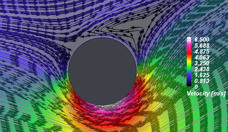
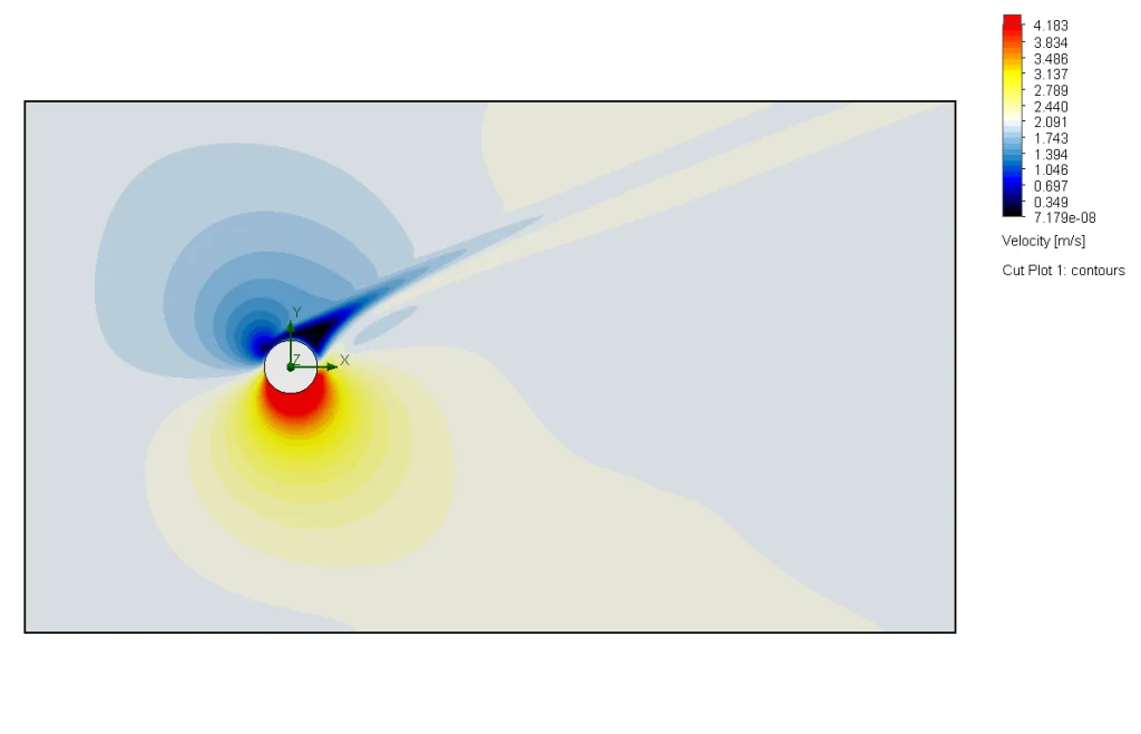
Pic. 1. Flow patterns along with the velocity field around the cylinder rotating at 600 rpm.
This effect has been associated with the boundary layer and fluid viscosity. It is common to hear that the velocity of Newtonian fluid on the wall is zero, but we should correctly say that the velocity of fluid relative to the wall is zero.
As a result, two zones are created on the rotating cylinder, a zone with an increased speed, where the speed of free flow is increased through the zone in which the fluid movement resulting from the rotation of the cylinder is directed towards the direction of free flow, and the zone where the phenomenon is in reverse state. We can observe it in Picture 1 where we see two zones around the cylinder, one with a high speed value, the other with zero. The effect of the speed field is the pressure field, which can be seen in Picture 2.
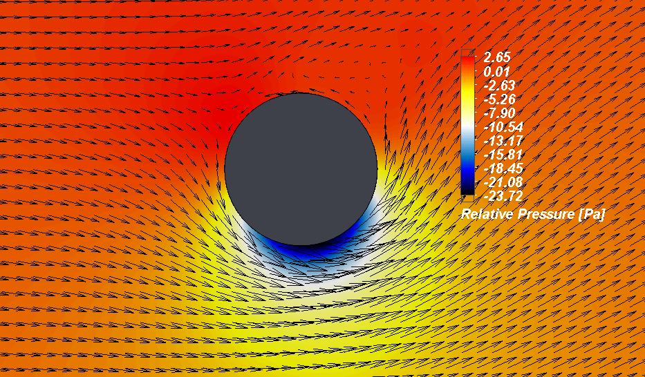
Pic. 2 Relative pressure field with velocity vectors.
These areas result in one side receiving negative pressure, while the other side receives high pressure. The pressure difference creates a force that deflects the flight path.
Using the phenomenon described in this way, a mathematical model was created:
F/L = ρvG
Where:
F/L – force per unit length of cylinder [N/m]
ρ – fluid density [kg/m3]
v – flow velocity [m/s]
G – turn force generated by turning the cylinder, which can be described by the equation below [m2/s]:
G = 2πr2 ω
Where:
r – cylinder radius [m]
ω – rotation speed [radian/sec]
This model, however, does not cover all phenomena participating in the process, so experimental results and simulations show a deviation from the model.
Studying the impact of rotational speed on the phenomenon
The Magnus effect, in addition to creating additional strength, also changes the flow around the object.
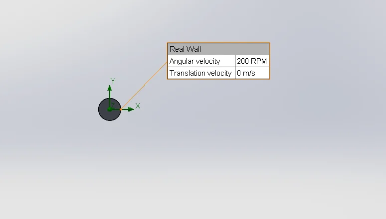
Pic. 3. Test diagram together with the wall rotation condition, the assumed free flow velocity is 2 m/s in the + X direction.
To show how the flow around the object changes and how it can affect the object, a parametric study was built where rotational speed is a variable parameter. The test scheme can be found in Picture 3. The tested rotational speed was set from 0 to 600 RPM.
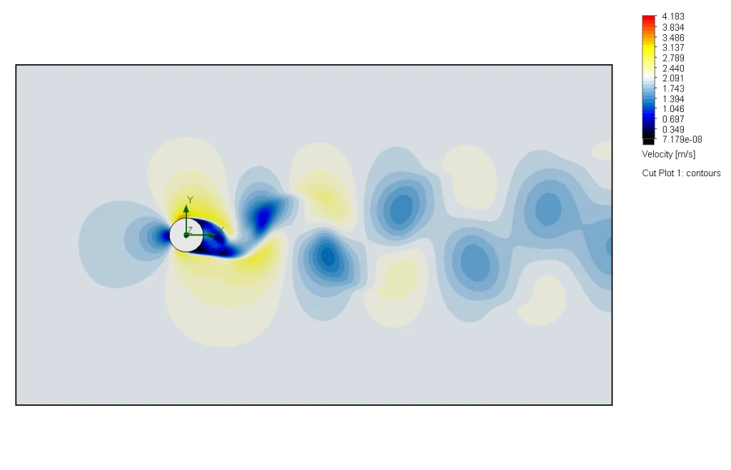
The free flow around the object for a given Reynolds number causes the formation of so-called Von Karmann vortexes, as a result we get force fluctuations in the Y direction, which for the object in flight will cause position fluctuations, and therefore the object will vibrate unnaturally. The rotational speed around the object changes the direction of flow behind the object, which minimizes these fluctuations. We can see this in Picture 4 where the speed field for rotational speed from 0 RPM and 600 RPM after 20 seconds with 100 RPM steps has been shown.
0 RPM
100 RPM
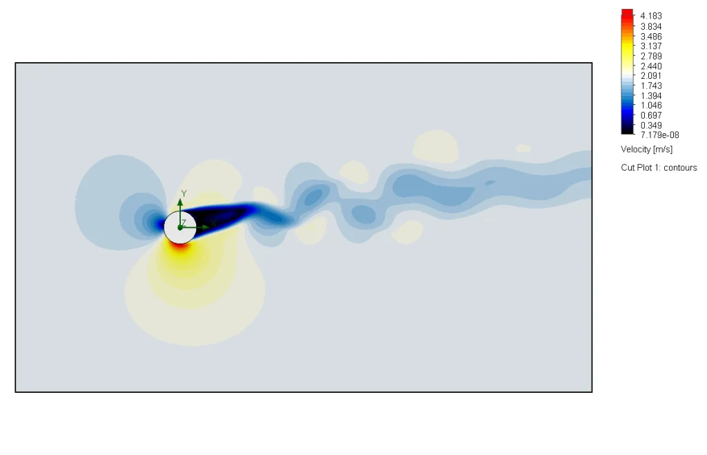
200 RPM
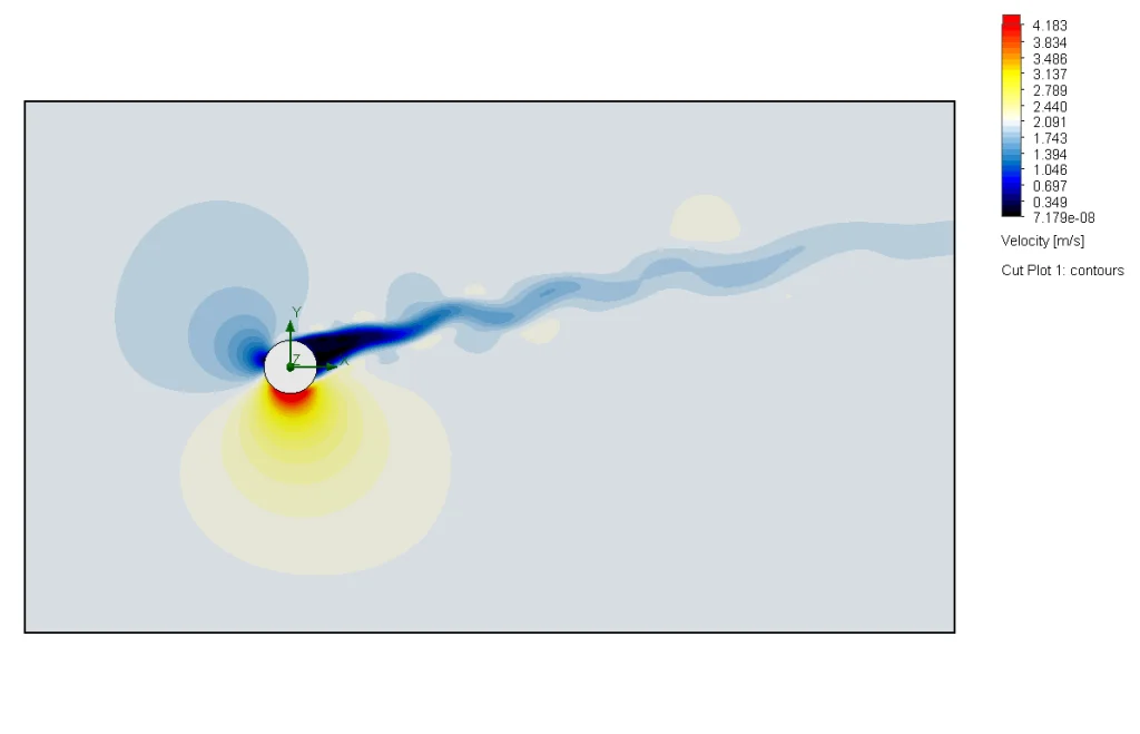
300 RPM

400 RPM
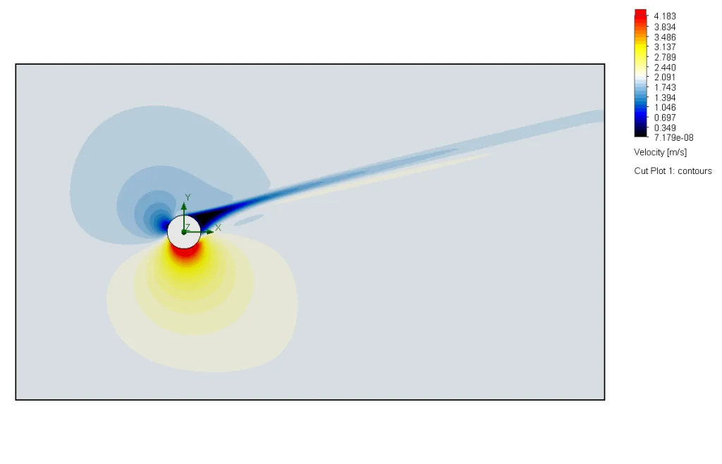
500 RPM
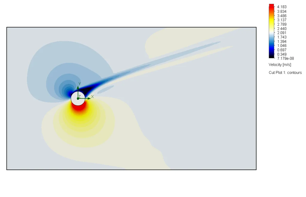
600 RPM
Pic. 4. Here we show the speed field depending on the rotational speed on the object from 0 RPM to 600 RPM in 100 RPM steps after 20 seconds of flow.
We can see that as the speed increases, the Von Karmann vortices disappear, which will result in less fluctuations in the object’s force in flight, and thus greater stability, as seen in the force versus time graph in Figure 1.
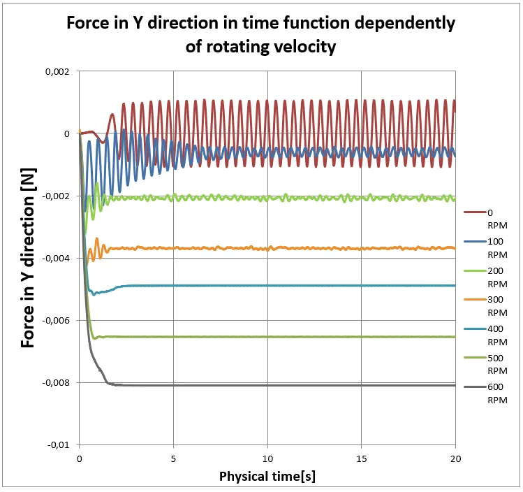
Graph 1. Graph of force in the Y axis as a function of time for various rotational speeds.
It is easy to see that the force increases as the speed increases. In addition, force fluctuations on the object itself are reduced. This is due to the disappearance of speed field variability over time, the flow for a high speed value is stable, relative to the flow without speed as we can see in animation 1.
Animation 1. Showing changes in the speed field for an element with no rotational speed and an element with a speed of 600 RPM.
Due to fluctuations, we need to use the mean value of forces for further analysis, so as not to mistakenly compare forces that could be read from a positive or negative peak.
Study of the impact of flow velocity on the described phenomenon
Thanks to the presented analysis, we are able to determine how the force in the Y direction is generated depending on the rotational speed, then let’s examine the generated force from the free flow speed. For this purpose, an identical parametric test was built, changing the flow speed from 2m / s to 10m / s in increments of 2 m / s. The reference example was the one where the rotational speed on the wall was 200 RPM. In such a way as not to eliminate the impact of turbulence behind the object. Due to the resulting circulation, which increases with increasing speed causing its illegibility. Thus, only a fragment of the resulting Magnus force from the speed value in diagram 2 will be visualized.
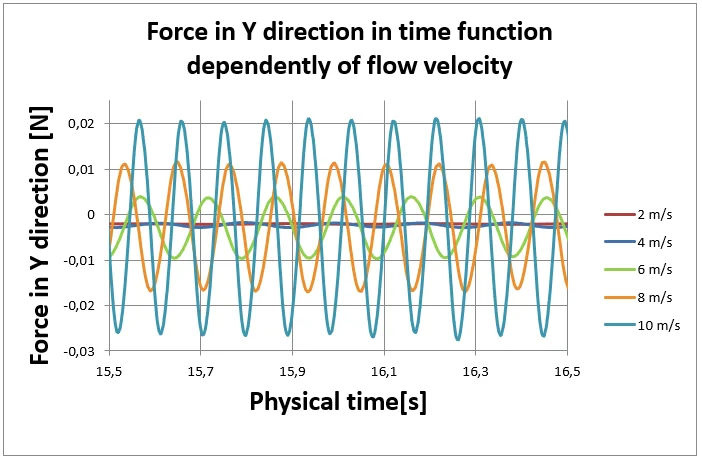
Graph 2. Graph of force in the Y direction versus time for different flow rates.
We can see here that the resulting Magnus force is just a part of the periodically recurring forces associated with Von Karmann vortexes, with their average value being 0, so we need to use the average value. We also see that depending on the speed, the functions have different amplitude and frequency.
Comparison of test results with the mathematical model
The last element of the phenomenon description is how the obtained simulation data differs from that obtained by the model. Parameters were compared depending on the rotational speed and flow speed with the data of the mathematical model in Graph 3.
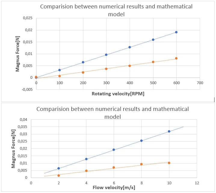
blue color – mathematical model, orange color – numerical results
Graph 3. Comparison of the results of numerical analysis with the mathematical model.
You can notice high deviations from the model both in flow speed and change in rotational speed, this is due to the fact that many aspects are not included in the mathematical model, namely viscosity forces or boundary layer characteristics, however, the model itself shows approximately the appropriate nature of the changes from the given parameters [1].
Summary
The Magnus effect is not only used to calculate the trajectory of objects, but it has its engineering application, one of the most interesting constructions using this effect is the Flettner Rotor. It’s a watercraft equipped with one or more large-size cylinders that can survive despite side winds. One of them can be seen in Picture 5. Attempts have also been made to use this effect to replace the classic wing of the aircraft with rotary rollers, however, the design was not safe enough, and the load-bearing components themselves were characterized by a temporary lack of thrust.
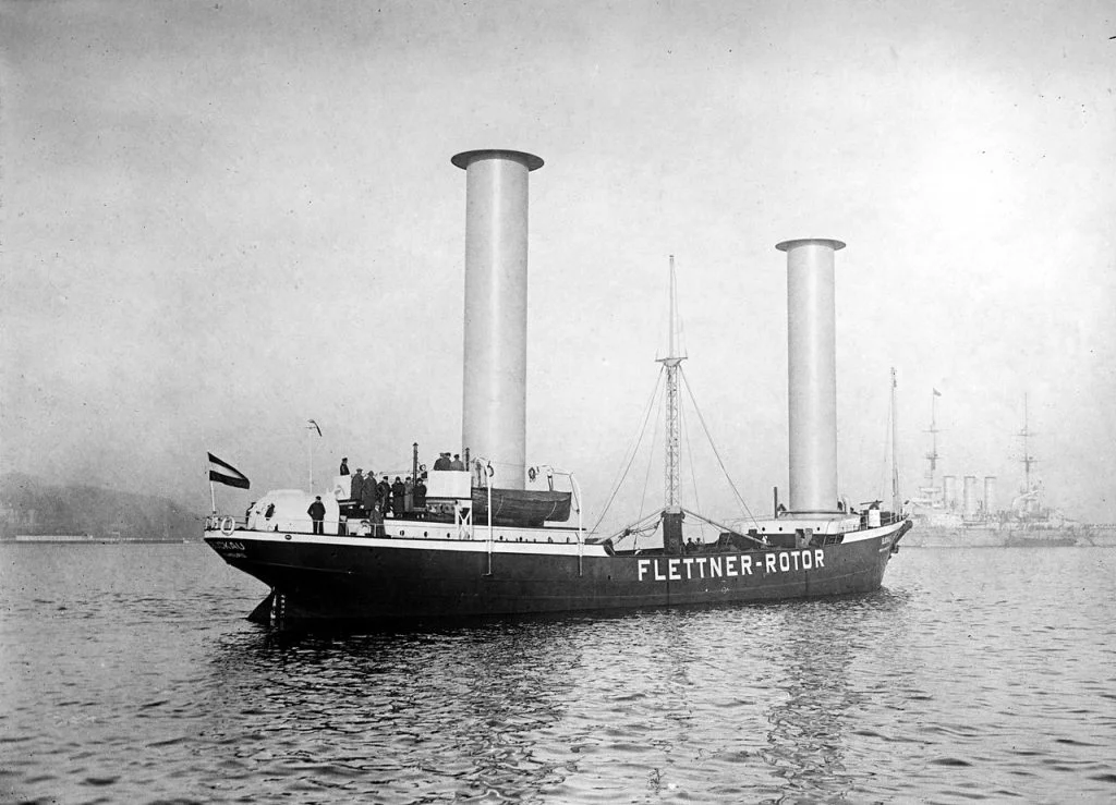
Pic. 5. The Buckau, a ship equipped with Flettner’s Rotor
[1]„Numerical Investigation of a Wind Turbine with Flettner Rotor Rotating on and Transversely to the Main Axis”, Uwe Borchert
Author:

Karol SUCHOŃ SIM/ CFD Technical Specialist | SOLIDEXPERT