

Introduction to Composites
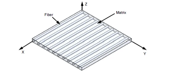
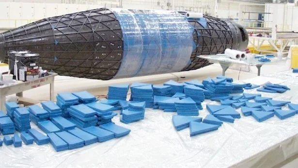
A composite material is a mixture of two or more materials. This is usually a stiff unidirectional fiber combined with a softer matrix element. The goal of such a mixture is to get desirable overall properties that each individual material could not provide. Composites usually exhibit good strength to weight ratio and is used primarily in the Aerospace and Biomedical applications or sporting goods like tennis racquets.
SOLIDWORKS Simulation Composite Analysis Capabilities
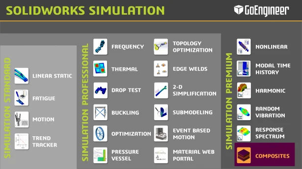
SOLIDWORKS Simulation Premium has the ability to perform a composite analysis. Users can perform a Linear Static, Buckling or Frequency analysis with composite materials.
Why use a Composite Analysis tool?
The main reason to simulate composites is that the material properties of a composite material is hard to calculate by hand. Just like simulation is intended to decrease the number of iterations needed, a composite analysis tool helps simulate different layer and angle configurations to see which material composition produces stress results that are acceptable.
There are failure criteria specific to Composites. Tsai-Wu and Tsai Hill are two composite failure criteria commonly used in the industry and these outputs can be seen using SOLIDWORKS Simulation. Finally, the stresses in each layer or the stresses between layers called interlaminar stresses may also be viewed to make critical design decisions.
Technical Deep Dive
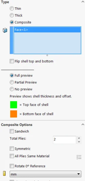
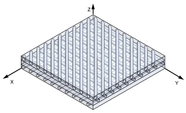
Let’s look at Composites from a technical perspective. Given the nature of where it is used, Composites are defined using Shell Elements. Hence, each composite part is assumed to have a uniform cross-section and a high length to thickness ratio. A maximum of 50 layers may be defined. The type of layups available with SOLIDWORKS Simulation are:
- Symmetric Laminate: Plies stacked symmetric about midplane
- Unsymmetric Laminate: Laminate does not exhibit Symmetry
- Sandwich Plate Laminate: Softer Core with a stiffer symmetric top and bottom layers
SOLIDWORKS provides self-learning Tutorial PDFs and access to self paced Training Files. Once a user has good knowledge of how a Linear Static Analyis and Shell Meshing works, these files should get them up and running with using Composite Analysis as well. SOLIDWORKS also has the ability to export results to other FEA software like Nastran and ANSYS.
Verification
Typically for aerospace companies, verification of any FEA tool is critical before they can start using it. SOLIDWORKS have independently verified the accuracy of the composite tools. Click Here for links to the verification documentation.

Manufacturing applications engineer Arvind Krishnan works at GoEngineer, focusing on finite element analysis and 3D printing. He completed his master’s degree in mechanical engineering at North Carolina State University with a thesis in Using Michell Truss Principles to find an Optimal Structure Suitable for Additive Manufacturing. Arvind enjoys playing tennis, badminton, racquetball, chess, and soccer; he is also passionate about hiking and cooking.