

We all know how amazing the internal combustion engine is. From weed wackers to cars to bulldozers, it powers much of the equipment that makes our lives convenient. However, the engine wouldn’t be as useful without a way to transfer its motion. Without a way to get the engine’s power to the trimmer head of a weed wacker, the wheels of a car, and the tracks of a bulldozer, the engine is useless. So, the drivetrain (that doesn’t get nearly enough credit or moment in the limelight) is just as important as the engine.
Any mechanical engineer of heavy machinery will tell you how much care and consideration goes into the design of mechanisms and drivetrains. One of those considerations is how the system vibrates when power is driven through it. If the system is not properly designed, vibrations may cause premature wear, cracks, or an unpleasant experience for the operator. In this article, we will study how a universal joint (U-joint) driveshaft system vibrates as it is turned with SOLIDWORKS Motion!
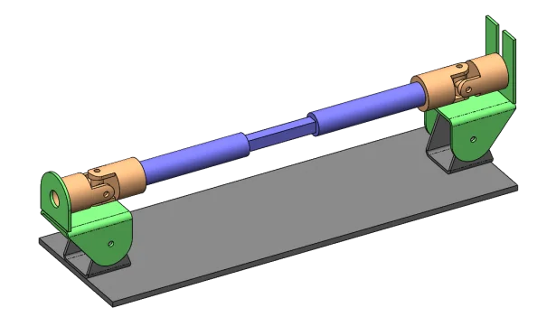
Let’s study this simple U-joint system. The U-joints are shown in orange and are comprised of a pair of hinges held together by a cross shaft. The joint shown in blue is a prismatic joint, which means the units are allowed to slide in and out of each other, but if one rotates, the other rotates with it. The joint shown in green is a pin joint and will allow us to adjust the input and output angles to do some testing!
Let’s suppose that we build one of these in real life and, when driving it with a constant velocity electric motor, the system is shaking. Can we find out why that is? With SOLIDWORKS Motion we can!
Here is going to be the set up on our model:
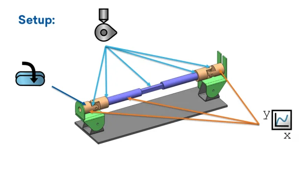
There are no fasteners on the model at all. This helps reduce complexity and will, instead, be taken care of with mates. Now for the fun part! Between each member of the drivetrain (i.e. from U joint hinge to cross shaft to U joint hinge to prismatic joint etc.) we will specify solid body contact. This is what tells SOLIDWORKS that they should not pass though each other. And what kind of experiment would this be if we didn’t take any measurements? Let’s place a sensor on each of the areas of interest: the very beginning of the drive train, another on one of the prismatic joints, and one on the very end. These sensors will measure rotational velocity at each point. Last, but not least, we place a motor set to constant velocity on the beginning of the U-joints. It’s a good idea to set it at a slow velocity so we can really observe the effects (like 5 or 6 RPM is good).
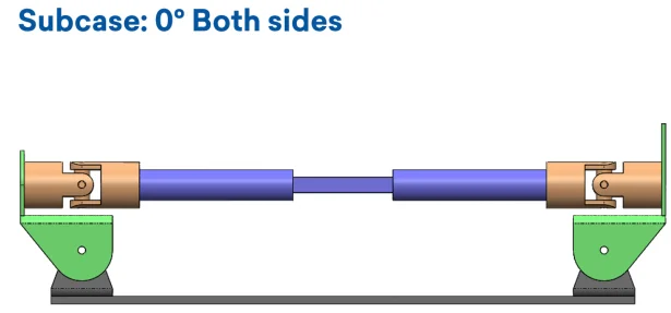
Now, we should test a simple case to see if it matches our intuition, verifying that the set up is correct. The simplest case to do is one in which both the input shaft and output shaft angle is parallel to the ground (i.e. zero degrees). Let’s see how this works!
What a twist (pun not intended)! The result is that the output not only remains sinusoidal, but it also gains magnitude! This is because we have moved the phase of how the two motions combine. Instead of harmoniously canceling out, they now add up. When one joint speeds up, the other also speeds up. This makes a more aggressive fluctuation in speed that causes a vibration. This is why if you ever take the driveshaft out of a car, you must mark the phasing to remember the exact orientation it went in. Otherwise, you’re in for a bumpy ride once the car hits the road…
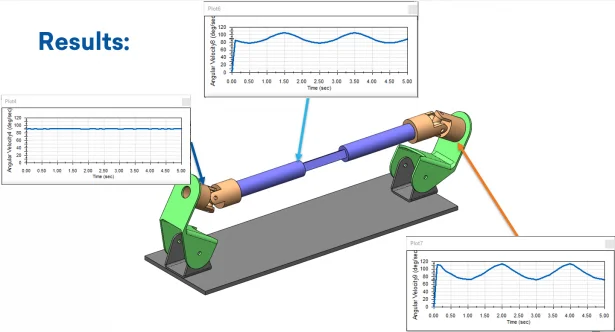
These results are important because even though the plots don’t directly measure vibration, they are enough to detect its presence and its overall magnitude. Since all the joints and the shaft have mass, changing its rotational velocity will cause inertial vibrations as indicated by the sinusoids. But one question remains. Are these results accurate, as in, does this phenomenon actually occur in real life? Well, let’s ask this guy because he will tell your part, your shaky breaky part! Thank you for following along!
Check out more blogs like this one here. You’ll find helpful articles and educational videos on a wide range of engineering and manufacturing topics to help you maximize efficiency in your job role!
And don’t forget to follow us on Facebook, Twitter and LinkedIn to stay up-to-date on our latest blogs, videos, promotions, and more!
Author: Robert Maldonado, Application Engineer at DesignPoint