Troubleshoot Meshing with SOLIDWORKS Geometry Analysis Tool
One of the most frustrating parts of the Finite Element Analysis (FEA) world is when a geometry won’t mesh no matter what you do. What’s even more frustrating is when you don’t know what to do about it! Luckily, I’ve found you can use the Geometry Analysis tool to investigate areas of your geometry that may cause your mesher problems. It’s such a helpful tool, I wanted to share it with everyone!
Goodbye, Frustration!
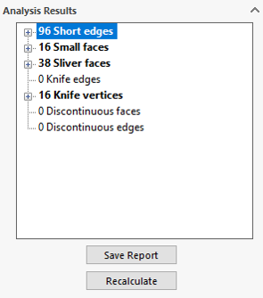
Often times, the main cause of mesh failure is due to very small geometry within a model. In those situations, the size of the mesh just can’t fit an element into that space, thus the mesh fails. The trick is to determine where that troublesome geometry is located in your model, especially as the design becomes more and more intricate. The Geometry Analysis tool does just that.
The tool analyzes the model and locates the very small features within the model. Once we have located the potential trouble areas, the combination of adjusting the mesh size and cleaning the geometry will help fix our meshing problems.

In order to determine the insignificant geometry tolerance, think about the shortest significant edge in the model. This could be the edge of a fillet, wall thickness, hole size, etc. Take this size, divide it by 2, and use the result as your tolerance value. A default of five for sharp angles usually works well.


Now that you know where they are located, you can either clean up the geometry for easier meshing in that area or try to apply mesh controls in those areas. Usually, that’s all you need to do successfully resolve a lot of your meshing problems!


