
Welcome to the “Creating a Belly Racer with SOLIDWORKS” blog series. If you need to catch up, you can start with the first one here.
In the last Belly Racer blog I wrote about the importance of the roll cage design and function in modern race cars. We used those design elements in the design of the Belly Racer roll cage and since the last blog much more work has been done.
One of the big changes we made extended the roll cage to the rear and attach it to the differential housing making it into a complete chassis. This approach makes the racer safer, stiffens the chassis and reduces the number of aluminum members and the associated welding. The reduction in the amount of welding was a secondary benefit and will help simplify the fixturing needed for the welding process. Even though each aluminum member is self fixturing using tabs and slots there will still be a need to hold members together while welding is accomplished.
Here’s what the new chassis looks like.
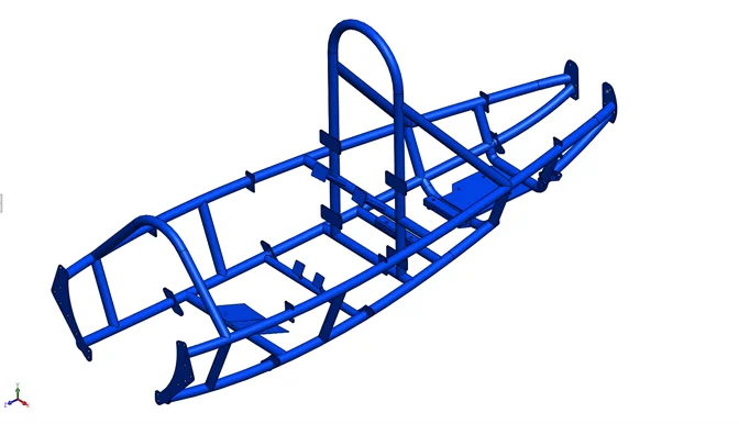
With this new design the driver, engine and driveline are cradled in a much stronger chassis. There were concerns with the previous design about chassis flex and twisting which could lead to welds cracking due to the flexing and resultant fatigue. The new design provides much better structural stiffness which will eliminate or greatly minimize any flexing and twisting.
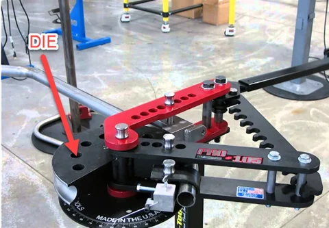
The material for the chassis/roll cage is 1 ¼” DOM or Drawn Over Mandrel mild steel tubing. DOM tubing is easily formed, has high yield and tensile strength and has good machining and welding characteristics. DOM tubing is formed using a manual tube bender as shown below. Power assisted tube benders are available but the cost is usually out of the range for a hobbyist. The tube is formed over a die which maintains the diameter of the tube in the bend area and prevents the tube from “kinking” during bending. The degree wheel is used to create accurate bends because not all bends are 90°. I have one of these tube benders in my garage which I used to fabricate a roll cage for a Porsche 924 race car. You can watch how a tube is formed here.
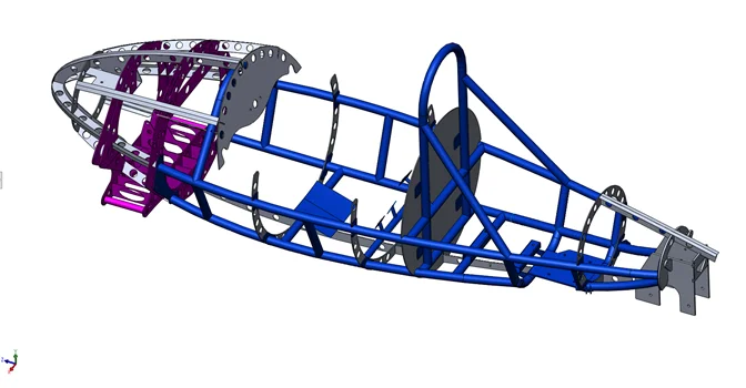
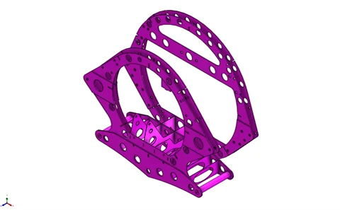
There were no changes to the original front structure. This is a separate assembly made entirely out of aluminum and TIG welded together. The ribs and bulkheads fit together using slots in each member so they are somewhat self-fixturing. Welding fixtures will be needed to hold the ribs and bulkheads together to ensure alignment of the suspension mounting holes through each of the main bulkheads indicated by the red arrows in the image below.
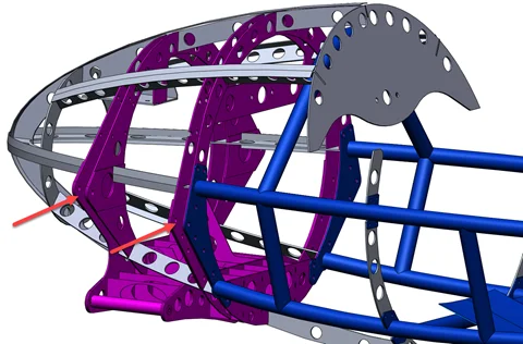
This is the main bulkhead assembly which makes up the main support structure for the front suspension, and steering rack. All of the front suspension components attach to this assembly so the accuracy of assembling and welding all of the components is important in order to obtain the correct suspension geometry.
In the next blog I’ll take a closer look at the engine, driveline components and rear suspension, and how they fit and mount in the chassis. Plus, I’ll describe why certain components were selected and how they work like the Continuously Variable Transmission (CVT) clutches and chain-driven differential.