
More and more engineers and designers are being called on to develop the look and feel of new products. The visual appeal of a product often plays a huge role in its popularity. Because of this, especially during the concept phase of design, you typically want to make several models quickly to get a clearer idea of what your customer wants.
Organic shapes are challenging to build with parametric modelers. If it takes you all day to create one concept and another day to modify it, you are two days in and still on that first concept. By leveraging subdivision (Sub-D) modeling, you can streamline the idea or conceptual stage of design because you don’t have to set up all the sub-structure (curves, surfaces, etc.) necessary in parametric modeling.
Both parametric modeling and subdivision modeling techniques are used to create the final models that will go into production. Often people assume that Sub-D modeling is only for the concept phase of the design, but this is not true. Models created using subdivision modeling techniques often go directly to production without re-creating the model using parametric surfacing techniques.
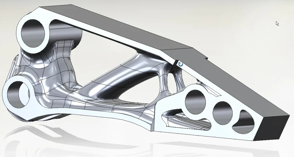
However, most often, models created with subdivision surfacing techniques are augmented with parametric features such as holes, chamfers, ribs, shell features, and more. The resulting model consists of geometry created using both parametric and subdivision technologies. Both technologies—subdivision and parametric modeling—have pros and cons. Taking a closer look at each technology will help to reveal what approach might be best for your projects.
Parametric modeling
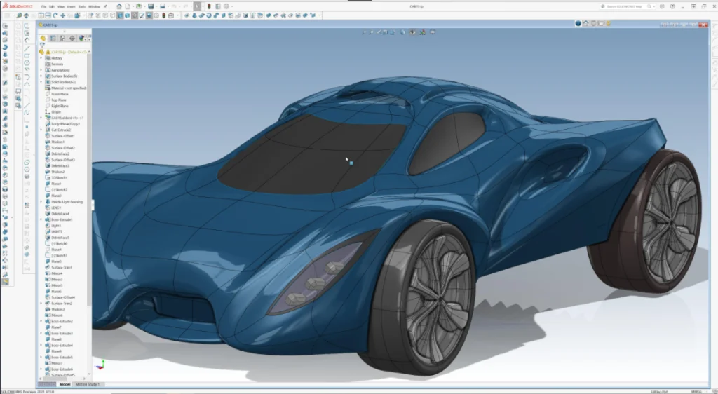
SOLIDWORKS® customers know all about the power of parametric modeling where you can drive geometry parametrically with dimensions—change one thing and the entire model updates automatically, no need to redraw models. You can embed intelligence in a design; these “smart” solids make it easy to share with other engineers who can quickly ascertain design intent. Plus, the constraints used in parametric modeling ensure that any modifications made to the design are done so with design intent in mind.
Parametric modeling is based on NURBS (Non-Uniform Rational B-splines). Surface geometry is solved literally with a network of splines driving the shape of the surface. Due to this method of generating geometry, surfaces can be precise as there is actual math driving the shape of the splines; this is why you can dimension it and constraint it. The curves that drive NURBS surfaces can be any degree: 1st (planar surfaces), 2nd (cylinder or conical), and 3rd (B-rep).
Subdivision modeling
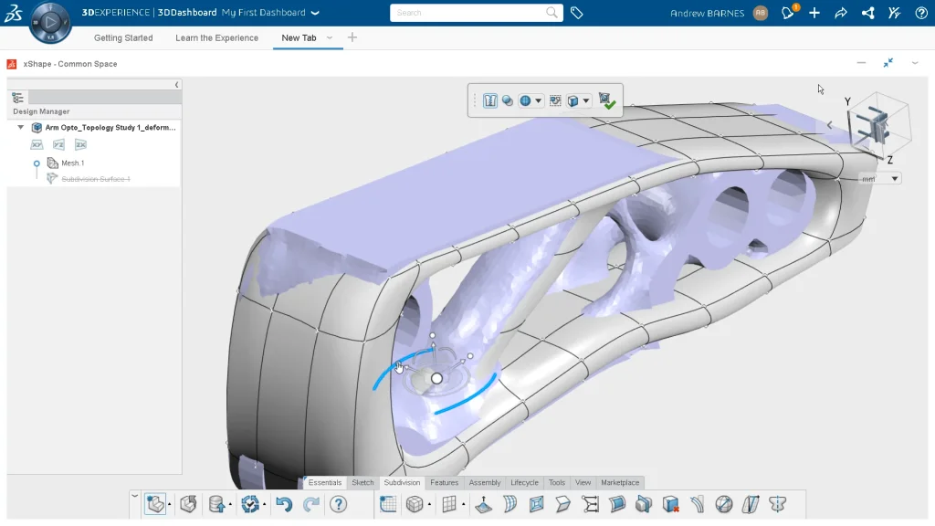
Many SOLIDWORKS customers are already enjoying the benefits of surfacing with the Sub-D modeling approach of 3D Sculptor on the 3DEXPERIENCE platform®. Surface modeling with Sub-D is superfast when creating contoured, ergonomic, and organic shapes. Making changes is so easy that there is no need to think ahead to make a detailed plan—3D Sculptor is conceptualization on steroids.
Subdivision modeling uses a method of generating a surface from a series of points in space. (Check out the Catmull-Clark algorithm that creates curved surfaces by using subdivision surface modeling.) The points are connected by edges, creating a mesh of rectangles. The surface is created by running a refinement scheme on the rectangular mesh, ending up with a smooth surface beneath it.
In 3D Sculptor, we convert Sub-D into NURBS, so it can be worked with just like any other CAD feature—cut it, shell it, chamfer it, etc. The automatic conversion to NURBS is extremely accurate to the original Sub-D geometry.

The Pros and Cons of Parametric Surfacing
Most of you are probably very familiar with parametric surface modeling. Typically, you create a substructure, like a skeleton, of curves, surfaces, planes, points, etc., to use it to loft and blend surfaces together. Combining this with the ability to intersect and trim surfaces allows you to create unique shapes that can be controlled parametrically by modifying the dimensions of the underlying skeleton features.
Many engineers and designers are very comfortable using these surfacing techniques, and they have proven to be a successful technique for decades. However, there are a few drawbacks to this technique. First, you must have a pretty good idea of the shape you are trying to create in advance. This probably means going through several conceptual test models and/or hand sketches to get to the point where you really want to put the extra time into making that final version. Even a small detail change like adding a blister-like crease to an otherwise smooth surface of a model may mean having to go back and recreate the original skeletal substructure, possibly resulting in hours of rework.
In addition, it can be difficult to create the smooth curvature continuous surfaces that so many designers want to create all over their models. Often they resort to filleting, which is an excellent technique for creating smooth surfaces, but won’t give the same results related to reflected light that you would get with a curvature continuous surface.
The Pros and Cons of Sub-D Surfacing
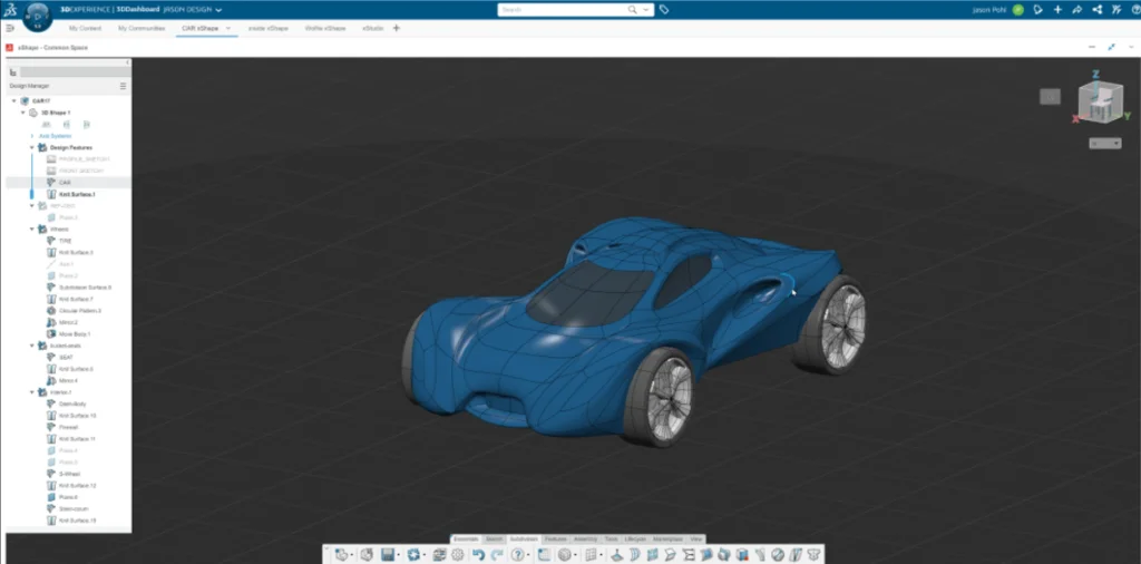
Less familiar to most engineers and designers is sub-D modeling. SOLIDWORKS 3D Sculptor provides Sub-D modeling capabilities in a browser. In Sub-D modeling, you can push and pull mesh geometry like it’s made out of clay to create your shape. Often you are designing around an assembly of 3D parts or designing with an image as a reference in the background, which gives you an idea of how far to pull and push the geometry. You also have features that let you create hard edges (for creases and flat surfaces). It is easy to augment the initial shape by extruding and bending geometry as well. And model scale can be controlled dimensionally by bounding box dimensions.
A big advantage to using Sub-D modeling is that you can develop radically different models quickly by simply pushing, pulling, extruding, and creasing geometry. The surfaces are naturally curvature continuous, giving an organic look, except in areas where you want creasing and flat surfaces. This makes working with end customers much more manageable—whether in person or a web meeting.
Radical design changes can be made in real-time, allowing you to collaborate with your customer to get the shape desired. Trying to do this when the model is constructed using parametric surfacing techniques typically results in taking notes or marking up a drawing or image for the design, hours of remodeling, and then another meeting. The ability to rapidly create several versions of the model is key to getting design buy-in from your customer earlier in the process and speeding up the final delivery.
But there are some disadvantages to Sub-D modeling as well.
Sub-D modeling is not great for making common features like holes, ribs, chamfers, etc.—features you typically find on plastic and cast parts. To add these features it is necessary to access parametric feature capabilities, as you find in SOLIDWORKS desktop and browser-based tools like SOLIDWORKS 3D Creator. Luckily, it is fast and easy to toggle back and forth between parametric and Sub-D modeling capabilities when using 3D Creator and 3D Sculptor—it is literally a click of a button. One moment you are creating parametric features and surfaces with 3D Creator, and then in the next moment, creating beautifully shaped subdivision surfaces with 3D Sculptor. 3DEXPERIENCE SOLIDWORKS gives you the best of all worlds in one offering: 3DEXPERIENCE SOLIDWORKS, 3D Creator, 3D Sculptor, as well as access to the 3DXPERIENCE platform.
Which is Better?
As stated above, both parametric surface modeling and Sub-D surface modeling have their advantages and disadvantages. But it is clear that, at least in the conceptual phase, Sub-D modeling can significantly improve getting to an agreed-upon design faster and easier than parametric surfacing. In addition, if changes to your model during the design/detailing phase require significant remodeling, it could also be advantageous to use Sub-D techniques because changes are faster and easier to incorporate. And finally, if your design is curvature continuous throughout the surface, it may also be advantageous to use Sub-D modeling instead of parametric surface modeling.
If you are a SOLIDWORKS desktop customer who already uses surfacing, then you should simply view Sub-D modeling as a new tool in the toolbox. However, the reality is that a combination of both Sub-D and parametric surface modeling is generally the best solution for most projects. Many users realize optimized workflows—sometimes getting projects done in half the time—by leveraging both SOLIDWORKS parametric modeling and 3D Sculptor’s Sub-D modeling.
More Information
3DEXPERIENCE SOLIDWORKS connects the industry-leading SOLIDWORKS 3D CAD solution to the 3DEXPERIENCE platform, a single cloud-based product development environment, and includes Sub-D and parametric surface modeling.
If you’d like more information on these products, contact your local reseller.