
We are crossing the halfway point in our DTV Shredder story where we get into virtual testing and prototyping. If you missed the previous blogs, you can get started here.

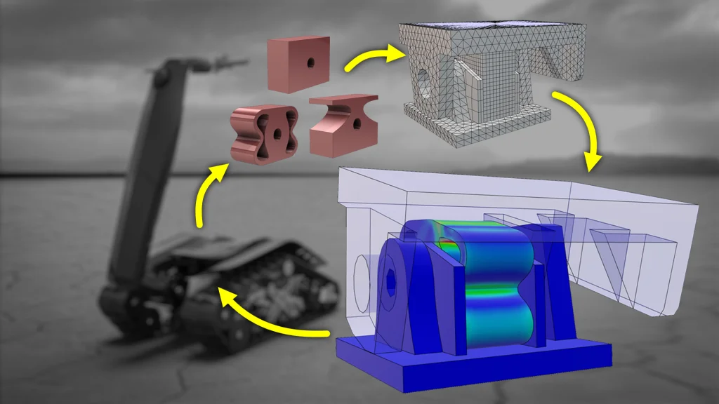
The DTV Shredder is all about the rider’s experience – and that is strongly influenced by the performance of the bushing on the pivot mechanism. How do different design options compare? We can test this virtually using the Structural Mechanics Engineer role on the 3DEXPERIENCE platform. Let’s see what it takes to prepare the geometry, define the scenario, create a mesh, solve and process the results.
Geometry Preparation
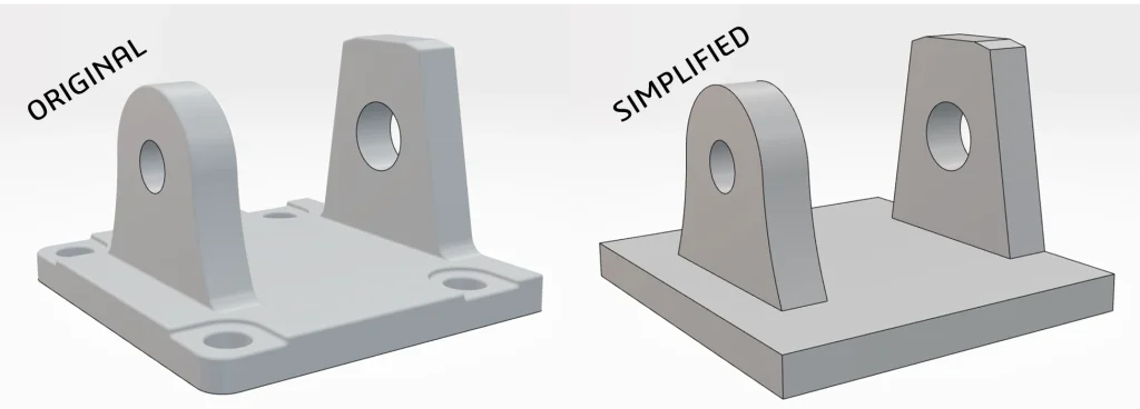
All the SOLIDWORKS models are stored on the 3DEXPERIENCE platform, so they’re accessible from the simulation app. Before running the simulation, we need to prepare the geometry. Any experienced FEA specialist can tell you that simplifying geometry is key in creating an efficient simulation study. This often includes removing small features that don’t influence the performance of a part. This task is easily completing by applying geometry filters to automatically find and remove the unnecessary holes and fillets in the model. Keep in mind that all these geometry modifications are separate from the source CAD model in SOLIDWORKS. However, if the CAD model changes, the simulation updates as well. It’s the best of both worlds.
Scenario Definition
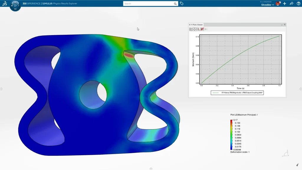
We want to determine the force required by the rider to impart a 15 degree rotation on the pivot mechanism. To solve for this value we define a prescribed rotation and an output request. Additional boundary conditions and properties are required. The built-in assistant makes it easy by walking us through the rest of the process.
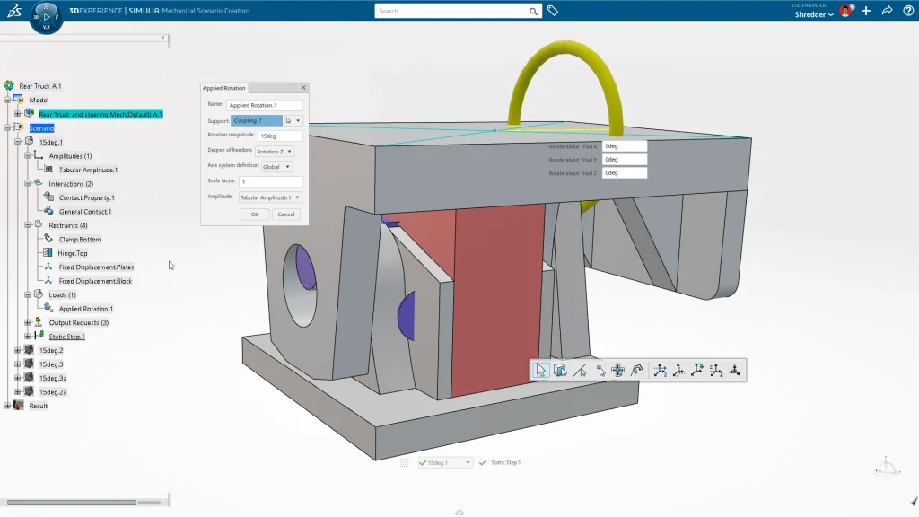
Another key element of the setup is specifying how parts interact with each other. Unlike other simulation tools, you only have to define one general contact condition. General Contact automatically finds and recognizes when parts come into contact throughout the course of the study. Simple, right? Manual contact definitions and multiple simulation runs to see if you got all of them are a thing of the past.
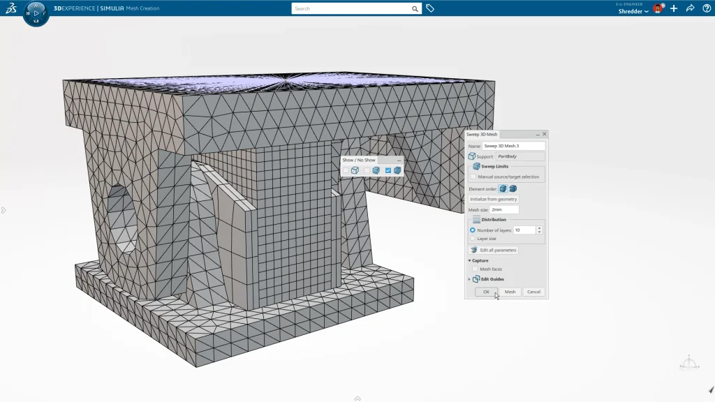
Meshing
The next step is meshing – breaking the model into small pieces that can be solved numerically to provide us with displacement, stress and strain results. A tetrahedral mesh is typically my go-to – it’s fast and efficient for most geometry types.
But for the bushing and guide plates, we use brick elements. They are better conditioned and computationally more efficient for the nonlinear hyperelastic rubber material of the bushing.
Solving and Post Processing
The simulation can be solved locally or on the cloud. That means flexibility and speed! When the simulation is complete, anyone on the team can view the results using their web browser.
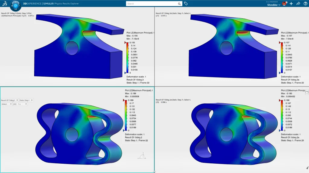
Comparing results from all the studies at once makes it easy to identify trends and provides a ton of insight on how to move forward with the design. To see more of how this simulation was set up watch this episode of SOLIDWORKS LIVE Design and be sure to watch the rest of the DTV Shredder video series.