
Metal 3D printing is not intended to replace traditional metal manufacturing processes. Rather, it’s a manufacturing tool that opens up new possibilities for product designers. There are many metal 3D printing technologies out there like direct metal laser sintering (DMLS), selective laser melting (SLM), electron beam melting (EBM). Each are fairly similar in how they build parts from atomized metal powders.
Parts can be built from powdered aluminum, Inconel, titanium, stainless steel, cobalt chrome, and more. The powder has the same chemical composition as the final part, since the process does not require any binding agents or additives. It’s essentially a microwelding process that results in a fully dense metal part with the mechanical strength and fatigue characteristics similar to a machined part.
Common uses of metal 3D printing include reducing multi-component assemblies into a single part and lightweighting designs with hollow features and internal channels. The possibilities may seem limitless but there are a few principles that you can follow to ensure quality results.
Basic Design Considerations for Metal 3D Printing
When designing for metal 3D printing it’s important to be aware that certain features are prone to warping or in-build curl if not supported. This is due to the internal stresses created by the rapid heating and cooling of the material during production. The design of support structures isn’t something you as a designer necessarily need to be too concerned with, but it’s good to know that some shapes are exceptionally difficult to build, and making slight alterations to your part design can be an easy way to not only improve quality, but also reduce manufacturing costs.
Tolerances. High-resolution DMLS at Proto Labs builds at a layer thickness of 0.0008 in. (0.02 mm) and can produce quite accurate parts, with tolerances to +/- 0.003 in. (0.076 mm), part features as small as 0.006 in. (0.152 mm), and surface finishes similar to that of a sand casting.
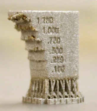
Wall thickness. At Proto Labs, our rule of thumb is walls below 0.040 in. (1 mm) must maintain a wall height-to-thickness ratio of less than 40:1. On the other hand, if walls are thick, it can be an inefficient use of material and build time leading to higher manufacturing costs. We prefer to hollow thick features out with a honeycomb or lattice structure in order to reduce material costs and processing time while preserving structural integrity.
Design Tips for Common Features
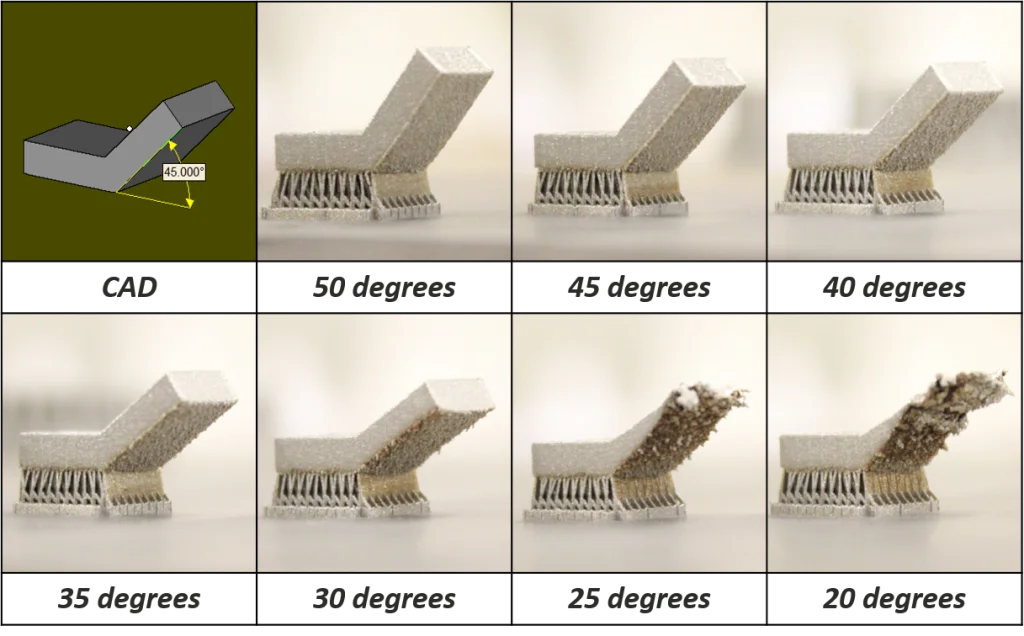
Self-Supporting Angles. A self-supporting angle describes the feature’s angle relative to the build plate. The lower the angle, the less the likely it is to support itself. Each material will perform slightly differently, but the general rule of thumb is to avoid designing a self-supporting feature that is less than 45 degrees. As you can see in the picture below, as the angle decreases, the features downward facing surface becomes rougher and eventually the part will fail if the angle is reduced too far.
Overhangs. Overhangs differ from self-supporting angles in that they are abrupt changes in a part’s geometry. DMLS is fairly limited in its support of overhangs when compared to other 3D printing technologies. At Proto Labs, any design with an overhang greater than 0.020 in. (0.5mm) will require additional support to prevent damage to the part. When designing overhangs it’s wise to err on the side of caution as large overhangs can lead to reduction in a part’s detail and worse, lead to the whole build crashing.

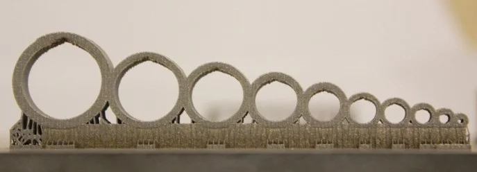
Channels and Holes. Internal channels and holes are one of the primary benefits of DMLS since they are impossible with conventional metal manufacturing methods. Conformal channels provide even cooling throughout a part and aid in reducing a component’s weight. We recommended that channels do not exceed a diameter of 0.30 in. (8mm). Similar to unsupported structures, the downward facing surfaces will start to distort as hole or channel width increases. A common workaround is to design channels with a tear drop or diamond shape. Channels that follow these shapes will make for a more uniform surface finish within the channel and allow you to maximize the channel’s diameter.
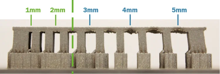
Bridges. A bridge is any flat down-facing surface that is supported by 2 or more features. The minimum allowable unsupported distance for our DMLS process is 0.080 in. In relation to other 3D printing technologies, this distance is relatively short due to the stresses of the rapid heating and cooling. In the picture below, you will see how the bridge pulls in the supporting structures as the unsupported distance increases. Parts that exceed this recommended limit will have poor quality on the downward facing surfaces and not be structurally sound.
Learning More About Metal 3D Printing
If you would want to learn more about how to design for metal 3D printing, check out our webinar “Designing for Metal 3D Printing.” You’ll find more details and tips on how to optimize your part design for metal 3D printing, select the right material, and reduce multi-part assemblies.