How to Design for Additive Manufacture


To me, great design can only be classed as such if it can be manufactured by a suitable, economically viable method. This is part of the challenge of design and one I have always relished. As additive manufacturing or 3D printing for end-use production parts becomes more economically viable, there is a perception that anything can be made with a 3D printer and to some extent this is true.
To maximize the potential of additive manufacturing, designs need to be optimized for the process. Printing a design that works for injection molding, machining or casting is possible, but rarely is it the best design for the process.
Roughly 12 years ago I was lucky enough to work in a design environment heavily involved with rapid prototyping. This was very handy when my sister broke my parents’ shower. The holder that attaches the shower head to the rail had been smashed by a falling shampoo bottle. This part formed part of a small assembly. The internals were all fine but the outer piece was cracked and could not be purchased separately.

I decided to model up the broken piece, taking measurements of the original and the internal parts, in SOLIDWORKS (2005) to be printed on the EOS SLS machine in a nylon powder. Since I only wanted one (or maybe an extra one as a spare), it actually worked out cheaper than buying a replacement holder assembly, not to mention the additional waste that would have resulted from the additional unrequired parts.
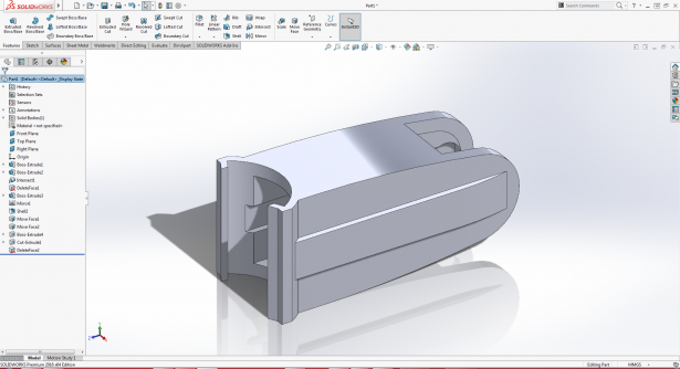
When I started modelling, rather than simply copying the injection-molded original, I thought about how I could improve the design by optimizing for 3D printing. Since it wouldn’t be injection-molded, I didn’t have to ensure all the walls were of even thicknesses, faces had appropriate draft angles or even consider a split line. This meant I could thicken and strengthen the part where needed and be thinner in other areas.

The main consideration on any 3D printer is that none of the features or walls are too small or thin to be made. Handily, SOLIDWORKS has a tool that can help. “Thickness Analysis” will highlight either thick or thin areas of the part you have on screen. I find for additive manufacturing it is most useful to uncheck the Full Color Range box as you only really want to see areas that are too thin to be made. It is obviously dependent on the machine and material you are using as to how thin you can go (and also how rigid you want it to be), but once you know, you are all set.
Once I had the replacement shower holder built, I took it home and sprayed it silver. In isolation, it perhaps doesn’t look like the prettiest thing in the world, especially considering I had no real design constraints, but I did need to get it done quickly and I wanted it to work first time. The main concern aesthetically was that it didn’t look out of place when it was refitted to the rest of the shower. As you can see in the photo, is that it is quite geometric so I wanted to keep that look too.

As for durability, well, the same part is still going strong over a decade later.
To learn more about optimizing SOLIDWORKS designs for 3D printing, watch this on-demand webinar, Best Practices for 3D Printing with SOLIDWORKS.