
Let’s continue the discussion after understanding two important concepts: Graphical PMI and Semantic PMI covered in Part 1 of this blog. Although graphical PMI is human-readable, it comes with many gaps: lack of associativity to models and no automatic update upon design changes. The biggest problem, however, is it breaks the digital thread in downstream production.
Let’s keep in mind: MBD is just a start, a preparation, or a prelude. The truly magnificent symphony is orchestrated in manufacturing, inspection, process planning, tolerance analysis and many more by machine-readable 3D PMI. Here are several examples:
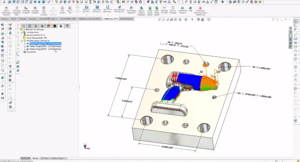
- In this first image you can see Tolerance-Based Machining by CAMWorks fully integrated into SOLIDWORKS MBD 2016. It reads semantic 3D tolerances and surface finishes defined in SOLIDWORKS MBD to automate NC programming including strategies, tools, speeds, and feeds.
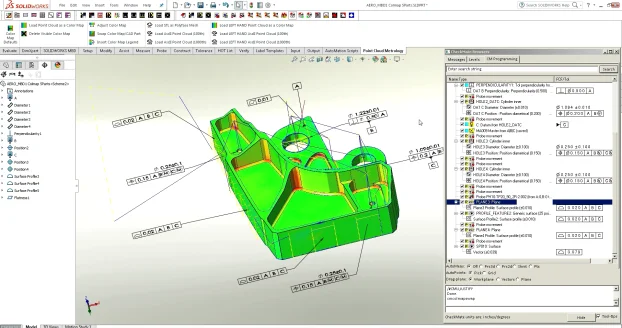
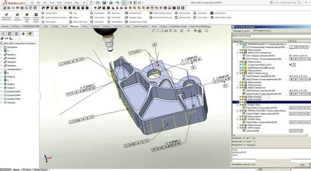
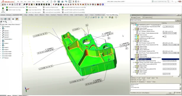
- After machining, CMM Inspection is shown in the images below. CheckMate by Origin International can read semantic 3D GD&T by SOLIDWORKS MBD to program CMM paths and soft gauges automatically, which cuts programming time from hours to minutes. Then CMM sample points or 3D scanned first article point of cloud can be compared with the nominal CAD model. CheckMate automatically generates a quality heat map according to the semantic 3D GD&T.
- There are more areas to automate by reusing semantic 3D PMI such as Tolerance Analysis, Computer Aided Process Planning (CAPP), and Work Instructions. Many SOLIDWORKS partners are working on them.
After a two-year pilot program from 2013 to 2015, Rolls-Royce concluded: PMI creation in the correct way is crucial for enabling true Model-Based Enterprise. Biggest savings will come from machine-interpretable PMI associated to model geometry. (Source: Technical Data Package for the Digital Enterprise, Kong Ma, Rolls-Royce Corp, 2014).
To support this initiative, ISO published a new STEP version AP242 to include machine-readable 3D PMI (Source: Industrial automation systems and integration — Product data representation and exchange — Part 242: Application protocol: Managed model-based 3D engineering, ISO 10303-242:2014). A side benefit of STEP is it supports Long Term Data Archival and Retrieval (LOTAR) requirements: LOTAR International completed a review of STEP and concluded that STEP is very stable for long-term archival (>70 years) and recommends the use of STEP for complying with NAS/EN 9300 (Long-Term Archiving and Retrieval of digital technical product documentation such as 3D, CAD and PDM data). (Source: STEP: STandard for the Exchange of Product model data, Allison Barnard Feeney and Thomas Hedberg, 2014).
In summary, it may be acceptable to start MBD projects with graphical 3D PMI at the beginning of an MBD implementation, enough for human interpretation, just like 2D drawings. However, the real power of MBD is to enable downstream automation by reusing machine-readable 3D PMI. So please don’t stop at graphical PMI. Try to gradually define semantic PMI to set up the stage for downstream intelligent manufacturing applications.
Next we will discuss the importance of templates and how to customize and standardize them. To learn more about how SOLIDWORKS MBD can help you define machine-readable PMI, please visit its product page. Also I welcome discussion on the topic at Twitter (@OboeWu) or LinkedIn (OboeWu).