Sigmund: Seven Steps to Guaranteed Product Quality in Design
Today, 3D CAD technology has matured to high levels of building complex designs. Validating the design for Fit, Form and Function (F3) are now completed with great care, upfront. Yet, Superior Assembly Build Quality, Consistent Performance and Low Cost Objectives have always thrown many a challenge to Manufacturing Enterprises. 3D CAD designs live in an Ideal World of congruence. Real parts and assemblies, do not – therein lies the problem How can we translate idealism to reality, keeping the above challenges in focus?
If Quality Issues are going to affect the F3, then why not address them upfront, at the Design Stage? This is exactly where Design for Product Build Quality comes into action. Designers rarely get to understand Manufacturing processes and their challenges, in depth. Manufacturing is always seeking ways and means to reduce setup time, cycle time and tool life, through Value Analysis and Value Engineering (VAVE) measures. While Inspection wants to reduce setup time, costs and improve yield. What good are these measures, if the final Assembly Build Quality, Performance Metrics, Overall Cost Objectives are not met?
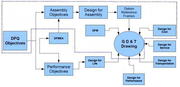
Design for Product Build Quality activity focuses on Assembly Build Quality and Consistent Performance with Low Cost solutions as the common denominator at the Design stage. Engineers need to understand Design for Quality (DFQ) Objectives, Design for Assembly (DFA) criteria, Design for Manufacture (DFM) considerations in addition to Design for Cost (DFC) constraints. They can also leverage on Statistical Process Control (SPC) data available with Quality and Supply Chain, to improve throughput and Yield, deliver on consistency and solve quality issues, upfront, even before it happens. The activity aids in developing an Expert Knowledge Base that can be leveraged throughout the life of the product. Companies adopting this approach achieve a fine balance between Cost of Precision and Cost of Poor Quality.
Lack of “Design for Product Build Quality” and Dimensional Control spawns real-world stories of flawed products, delayed market launches, unaffordable product cost, depleted profit margins and finally, short-lived products or companies. An example of this: a VP of Operations in a Gear Box manufacturing unit could not enter his office, since it was full of rejected gearboxes with assembly issues! Specialist Workers were there, with deft skill sets, performing selective assembly by trial and error which impacts on Profitability and Competiveness!
How Design for Product Build Quality Process Works?

Step 1: Define DFQ Build Objective
A measurable specification (Qualified & Quantified) reflecting DFQ Objective has to be clearly defined. This could be Gap, Clearance, Flushness, Mis-Alignment, Parallelism among others.
Step 2: Identify Dimensional Contributors
If an assembly comprising of requisite parts (that satisfy the DFQ objective) are correctly and completely dimensioned and toleranced (using Plus/Minus and/or GD&T Schemas) then it would become easy to select the contributing dimensions with clarity and ease. For this, it is imperative that the Datum Reference Frames (DRF) are clearly defined, reflecting the Assembly sequence.
Step 3: Define Vector Loop
Based on Plus/Minus and GD&T schemes employed on the part definitions, Tolerance Vector Loop is defined between the features participating in the measurable specification, across parts that define functional assembly
Step 4: Perform Tolerance Stack Up or Variation Analysis
Choosing Tolerance Analysis methods (Worst Case, Root Sum Square, Modified Root Sum Square, Process Centric Root Sum Square and Monte Carlo) nominal values and tolerances of the measurable specification are calculated.
Step 5: Identify Critical-To-Quality Contributors (CTQs)
Establish CTQs (or Key Characteristics) from the Sensitivity Plots of Dimensional contributors.
Step 6: Define DFQ specification and allocate tolerances for least Cost to meet the requirements
Desirable limits of DFQ specification are specified, Sigma Level is chosen, standard component dimensional contributors are ‘locked’, Cost of Precision is specified as a Weightage factor, Process capability (if available) is included, and allocation of tolerances for least cost is completed.
Step 7: Repeat for all DFQs and Optimize Tolerances
After completing all DFQs, Tolerance Optimization is performed for least cost across vector loops while prioritizing CTQ (KC) criticality across objectives. 3D CAD model is automatically updated and drawings with CTQ’s are released. Parts produced are then monitored for the CTQ’s to ensure consistent quality.
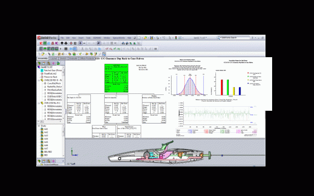
These simple steps are a surety for success in meeting and/or exceeding customer quality objectives. By incorporating Process Capability in Step 6, during production, maximizing the yield is assured. Benefits of Sigmund’s Design for Product Build Quality approach include: A snapshot of Sigmund performing variation analysis and reports is also shown below in Fig 2.
- Achieving First Time Right
- Least Cost Tolerancing
- Consistent Quality in Assembly Build and Performance
- Upfront Dashboard of Quality Indicators, Yield and Assembly health
- Satisfied Customer

To learn more about Design for Product Build Quality Process and Sigmund Software/Consulting, you can call Varatech Inc., and/or EGS Pvt Ltd.


