
Last Saturday I attended a workshop on a well-known software specialized for steel & reinforced concrete structure design and analysis. After attending this session, I had a clear understanding that the SOLIDWORKS workflow can improve structure design and validation processes by leaps and bounds.
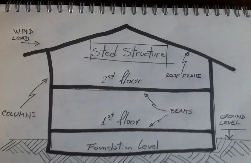
The presenter, a specialist of 10-years, developed the following case study: a two floor steel structure building under permanent load, wind and seismic loading.
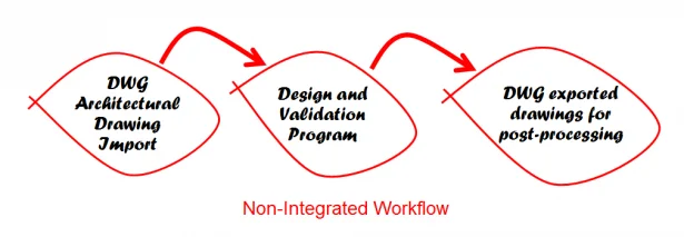
The deliverables for this project were drawings and analysis reports. Below, are the workflow process used in the workshop.
After three hours on the project, the presenter was at the architectural drawings (DWG) import step and just started working on the main floor settings, which includes section assignments for columns and beams. At that point, we completed only 25% of the total deliverables for the project. Therefore, the job required approximately 12 hours to finish.
This reminded me of my previous career working as a large structure analyst. I often used a variety of dedicated structure software with the same problems I experienced in this case study:
- delays in the drawing import and export processes
- engineering changes taking more than one day to be done
- lack of an integrated solution
- poor documentation quality control
Today, working as a technical manager for SOLIDWORKS Latin America, I often help my clients with these types of problems and make them more efficient with their structure design and validation process.
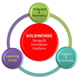
So, working in the field with customers, I have identified three key characteristics for a software solution to be productive:
- Integration & Parametric: import and export processes are no longer necessary.
- Learning Curve: Intuitive and easy to use.
- Support & Community: https://my.solidworks.com/
I wanted then to know how much time it will take to have the same deliverables in SOLIDWORKS. So, I used the following workflow:
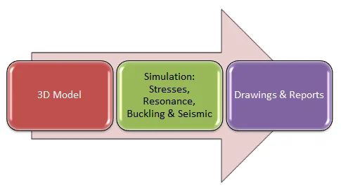
- 3D Design made in SOLIDWORKS 3D CAD.
- Analysis made in SOLIDWORKS Simulation, structural analysis tool (FEA) fully embedded in SOLIDWORKS 3D CAD.
Below is the SOLIDWORKS 3D structure full model:
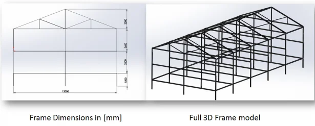
As this SOLIDWORKS model is a parametric model, it allows me to easily make engineering changes in a fraction of a minute and re-run the simulation on the full model without extra effort. Once the 3D model was designed in SOLIDWORKS 3D CAD, I could benefit from the CAD embedded structural tools, including SOLIDWORKS Simulation, to test this structure for stress, frequency, buckling and seismic resistance.
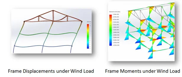
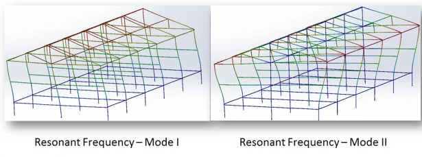
Below are some of the final Simulation results for this model.
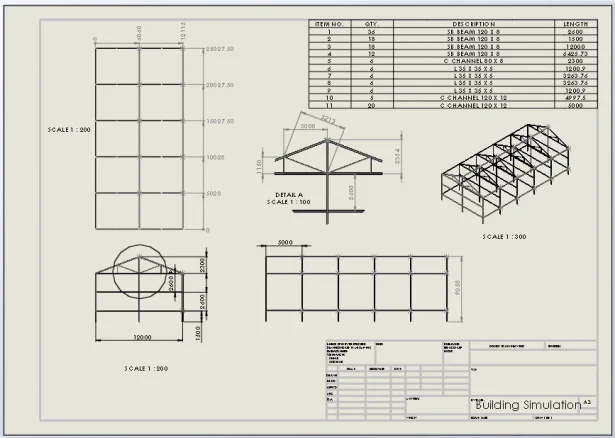
For reporting, I could easily document all aspects of the studies and the drawing has been completed done in a matter of minutes.
I started from scratch creating the structure’s 3D model. Focusing on the case study mentioned above, it took me only four hours to get the job done completely. So, I got the deliverables three times faster than with the software used in the original case study.
In summary, having an integrated platform allowed for me to be more efficient in terms of the structure design and validation process as well as provide a workflow to that pushes projects to production at a rapid pace.
To learn more about SOLIDWORKS Simulation please visit; www.solidworks.comsimulation