
A common question we often get regarding post processing of a SolidWorks Simulation study is: Does SolidWorks Simulation have a way of displaying displacement plots as angles of displacement in the case of a torsional load? SolidWorks currently does not have this capability directly but allows us to display tangential displacements with respect to an axis. From this we can simply apply the arc length formula, S=?r, to get our angular displacement. Let’s take a look at how this done in SolidWorks Simulation…
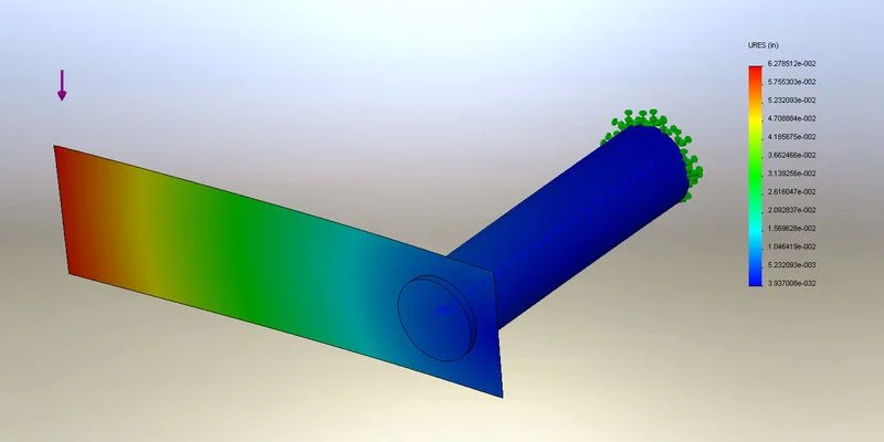
For the purpose of illustration we will use a simple torsion bar with an offset transverse load as an example. As you can see below, we have the transverse load applied to the end of a plate attached to the torsion bar which will cause a both a bending moment and torque on the bar. Our goal here is to determine the angular displacement resulting from the torque on the torsion bar.
As you can see we have the load applied to the end of the plate and have fixed one end of the torsion bar. After running the analysis and looking at the default displacement plot we can see the resultant displacements. This however does not do us much good if we are looking for angular displacements. You may or may not know that under the “Advanced Options” while creating a new plot, you can define a reference plane, axis, or coordinate system. Anytime you select an axis as your reference SolidWorks automatically switches to polar coordinates. For the case of displacements we want to define a UY Displacement plot and use the axis that we want the displacements about as the reference; this will give you a plot of tangential displacements (UX and UZ give radial and axial displacements respectively).
Now that we have tangential displacements about our axis of torque we can apply the arc length equation to solve for the angle of displacements. The best way to find out the displacement at a particular point is to “Probe” a particular place on the plot. This can be done by right clicking the plot from the Simulation tree and going to “Probe”. You can then select any point(s) on the plot that you want to know the angle of displacement of.
I have selected the point where the load is applied as my probe location. The probe command displays the tangential displacement at this point as well as the coordinates of the point. We know the coordinates of the axis, so we can apply the distance formula to determine the resulting distance between the axis and the point. Using this value we can divide the tangential displacement value by the distance we just calculated to get the angle of displacement.
If you want to know the angular displacements at multiple locations you can probe multiple spots or probe using “on selected entities” to get the tangential displacements at every node along an edge, for example. The values then can be exported out into a CSV file and used in excel to do the above calculation for all points.
Hopefully this can be of some benefit to those of you who have pondered this very question. If you are interested in seeing further how excel can be utilized for these calculations, you can download the sample files that I’ve used here. These files include an excel document that shows how formulas can be leveraged to calculate angular displacements for the edge shown above.
***
Chris Olson is a Technical Services Engineer at Graphics Systems, a SolidWorks Value Added Reseller with locations across Wisconsin and Illinois. He is a regular contributor to the Graphics Systems’ blog: SolidNotes.com, your source for SolidWorks, Simulation, Data Management, & Product Communication Tips & Tricks.