Preparing SOLIDWORKS Models for 3D Printing


From SOLIDWORKS to Prototype – Preparing your model for 3D Printing
3D printing is a topic that’s in the forefront every designer and engineers mind nowadays. The ever increasing array of technologies and cost effective solutions available on the market, mean that the option to use prototyping equipment to prove a design is more readily available to us than ever before. So once we`ve used SOLIDWORKS to finalise those last design details, how do we successfully make the transition from SOLIDWORKS to a 3D printed model?
STL files
STL files are widely accepted as the industry standards when it comes to rapid prototyping. It is the one single format that can be output by most CAD programs that can be understood by the vast majority of prototyping equipment.
So what is an STL file?
STL or Standard tessellation/triangulation language is a 3D file format which uses a series or triangles to describe the outer surfaces of a 3D model. There is no colour, texture or additional attributes i.e. features. How do I create an STL file?
This is really easy. With your part (or assembly) opened inside SOLIDWORKS simply click file>save as to open the usual save as window. Then use the drop down to select .stl from the list.

This method of saving a .stl file will generate the file with the default resolution settings. However these settings may not suitable for your printer and could have a negative effect on the quality of your 3D print, so you should consider if you need to make any changes to ensure you have the correct settings.
What are these settings and why do we need to control them?
I like to think of these settings as “resolution” or “accuracy”. In simple terms, if you consider the idea of converting a perfectly round sphere (which is your SOLIDWORKS model) to sphere constructed of triangles (your .stl file). The bigger the triangles the coarser the resolution of your .stl file and vice versa.We have the ability to control how these triangles are created when the .stl file is generated, so we choose how coarse or fine the model is. But why? There is one main reason why we should think of controlling these settings, and this is because it can have a direct effect on the quality of your printed 3D model. If your settings are too course compared with the resolution of your 3D printer, then the printer will be able to print the definition of the triangles and your model wil appear faceted, deviating away from the shape of your intended design. If you set your model too fine, although you won’t suffer from poor quality models, the likelihood is that you will have a large file that takes a long time to
process and can be more difficult to handle.
So how do we control these settings?
In the save as window, once you’ve selected .stl as the save as type, an options box will become available. Click options to adjust the settings

ASCII vs Binary
You have the option to save STL files in either binary or ASCII format. Binary files are smaller (by a factor of 6!), so this format is usually preferred. However, ASCII files can be visually read and checked.
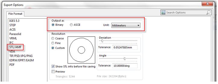
Resolution settings
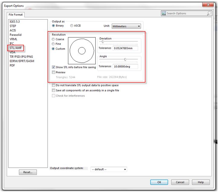
Within the resolution settings there are two default options (coarse and fine) as well as a custom option. Depending on the printer resolution, it may be the case that the coarse and fine options are too close to either end of the scale to be practical. Choosing the custom option will allow us to control the resolution to be exactly what we need.
We have the possibility to control both the deviation and angle of the triangles during .stl conversion. Deviation is expressed as a linear dimension and refers to the maximum distance that the facet of the .stl file is permitted to be away from the original geometry. The angle setting refers to the angular deviation allowed between adjacent triangles.
The image below illustrates how different resolution settings can affect the converted model. Taking number 1 as the intended design (SOLIDWORKS model) and number 3 as the best possible resolution 3D printed model. Setting a coarse resolution (Number 2) will mean that the printer, having a finer resolution will be able to physically print the facets, leaving you with an un-accurate model with visible facets. Choosing a very fine resolution (Number 4) means that the file may be overly large, difficult to handle and will almost certainly take longer to process than necessary. Number 3 in this case is the optimal resolution. The settings made in SOLIDWORKS match that of the printer, meaning the best possible 3D printed model and the most efficient in terms of file size, handling and processing.

Which settings should you choose?
This all depends on the resolution of the printer you’re using. Because there are so many printers to choose from these days, my best advice would be to take a look on the manufacturer’s website where you can normally find advice on the best resolution to choose.

Don’t forget with windows 8.1 and SOLIDWORKS we can now print directly from SOLIDWORKS!
https://www.solidworks.com/sw/products/3d-cad/print-directly-to-3d-printers-3mf-and-amf-formats.htm
Nick Jones
Solid Solutions Management
Applications Engineer
Latest posts by Solid Solutions Technical Team (see all)
- Hybrid Mesh Modelling in SOLIDWORKS 2022 - January 26, 2022
- Tips & Tricks for Structure Systems - March 4, 2021
- Windows 7 End of Life – How will this affect SOLIDWORKS? - February 3, 2020