

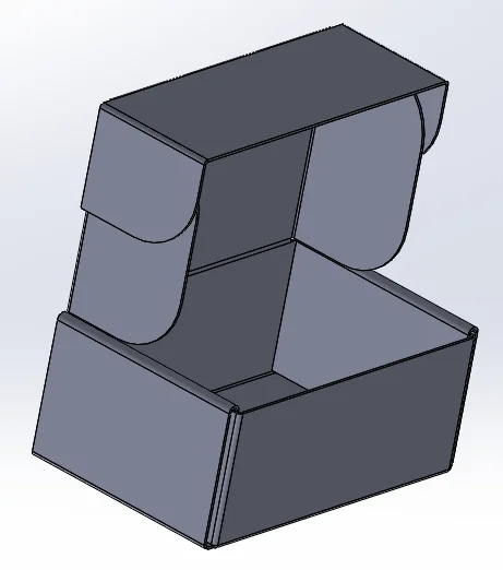
Being an intern at Dassault Systemes 3DEXPERIENCE Lab, I get many opportunities to test my design skills. For example, the IT Department at our Waltham office requested an improved cardboard box for shipping phones and other small items to employees who are working in other locations or traveling. The IT Department wanted to replace the boxes they were previously purchasing because of their cost and lack of durability.
Having used SOLIDWORKS Sheet Metal to design a variety of automotive and HVAC parts, I saw the potential to apply it to a cardboard packaging design problem. While SOLIDOWORKS Sheet Metal isn’t typically used for cardboard packaging design, the robust and versatile software met my needs for the task.
SOLIDWORKS Sheet Metal is a tool within SOLIDWORKS that allows you to create sheet metal parts, insert sheet metal bends into a shelled part, and convert solid parts to sheet metal parts.
When designing sheet metal parts in SOLIDWORKS, you can create the model as an individual part, in the context of an assembly that contains the components the sheet metal will enclose, or within part document in a multibody environment. I chose to design this cardboard box as an individual part because the shape of the sheet metal part I was creating wasn’t complex and it did not depend on the shape of an enclosed component.
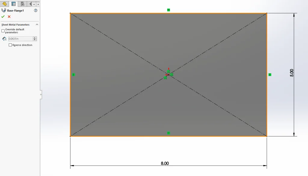
When designing a sheet metal part as an individual part, the first step is to create the base flange.
This was done by creating a sketch of the top view of the base of the part and setting the material thickness.
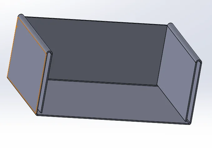
To add the sides to the box, the Edge Flange tool was used. One edge of the base flange is selected as the flange profile and a variety of parameters are set such as angle, flange length, and flange position.
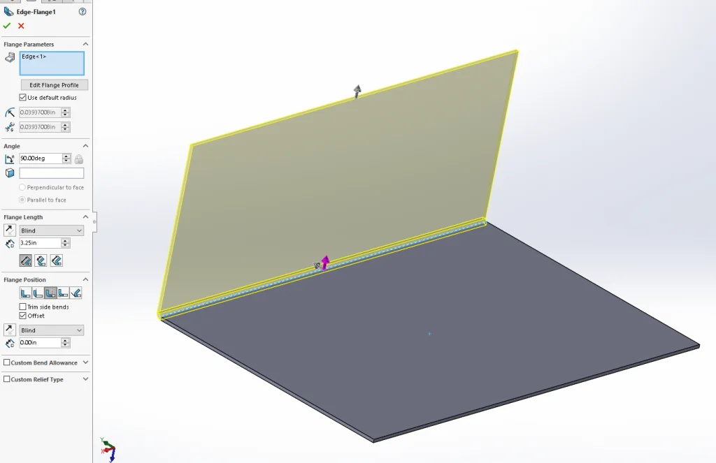
To continue building the sides of the box, the edge flange tool was used to add more structural folds to the first edge flange and more sides to the base flange.
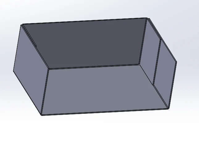
The hem tool was used to create a tab to hold the sides of the box together and provide a slot that will receive tabs from the lid to hold the box shut when it is closed.
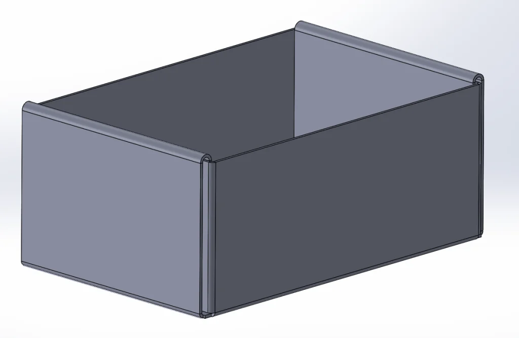
Next, the last side of the box was created using the edge flange tool.
Once the design in SOLIDWORKS was complete, the flatten tool was used to unfold the box into a flat part. The flattened shape of the box was then saved as a DXF file.
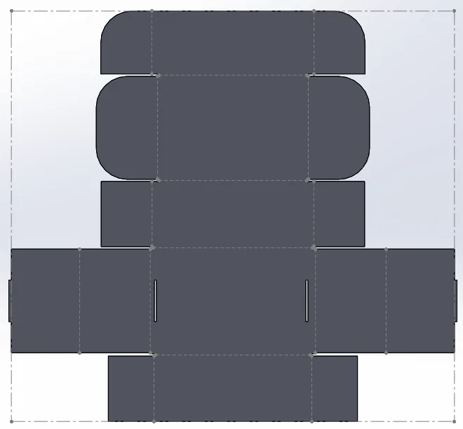
This DXF was then opened in Adobe Illustrator and the line weights and colors were adjusted so that Trotec Job Control would treat them as cut vectors. The dashed lines on the flattened part are the bending lines.
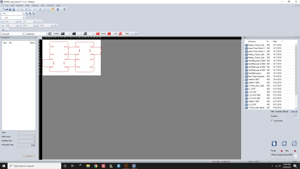
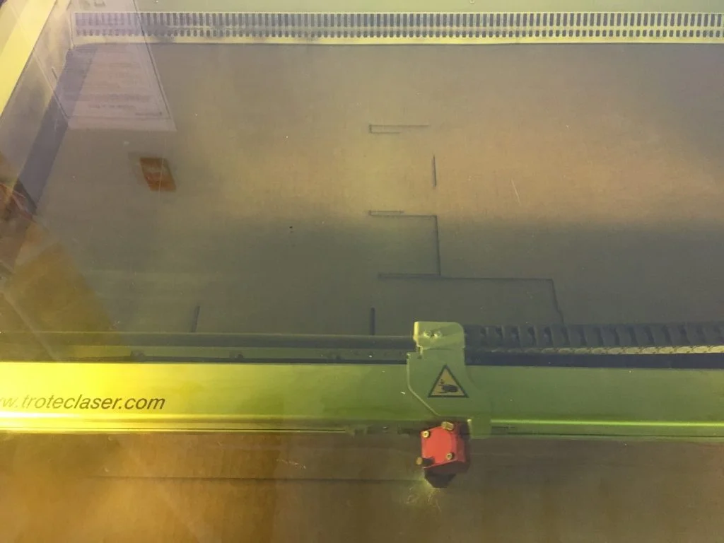
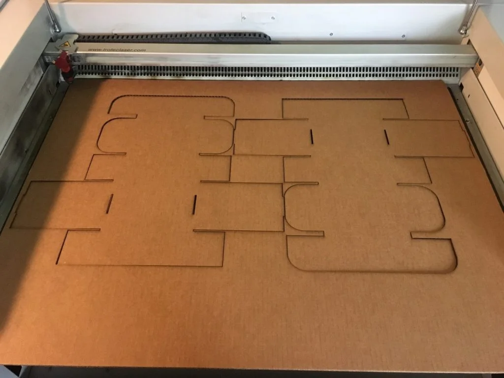
The box was then cut out of 1/8” Corrugated Cardboard on the Trotec Speedy 400 laser cutter in the 3DEXPERIENCE Lab at DASSAULT SYSTEMES in Waltham.
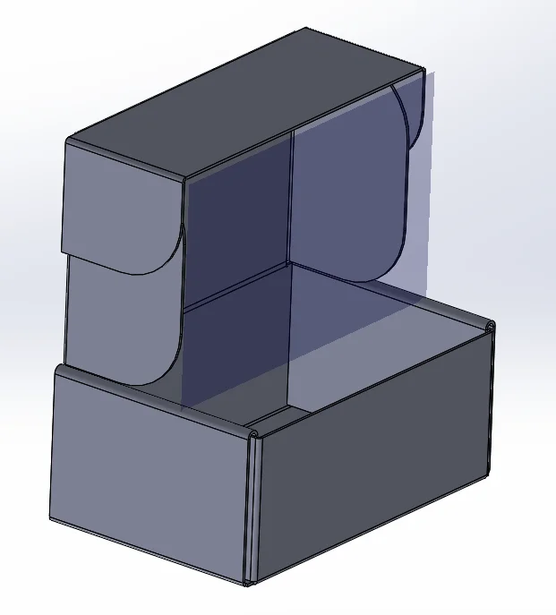
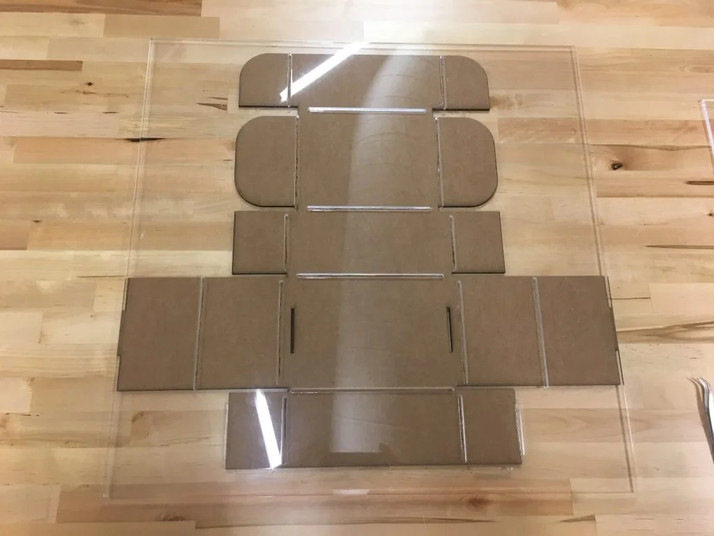
One helpful feature of the SOLIDWORKS Sheet Metal Flatten Tool is that it produces a sketch called Bend-Lines. The Bend-Lines sketch contains construction lines on top of the flattened model which represent the center of the bends in the folded model. This sketch was used to create another SOLIDWORKS Part file which contained the bending template. The slot sketch tool was used to place slots on top of the bending lines and then was extruded to the thickness of ¼” acrylic. Slots were also added to position the cardboard under the bending template.
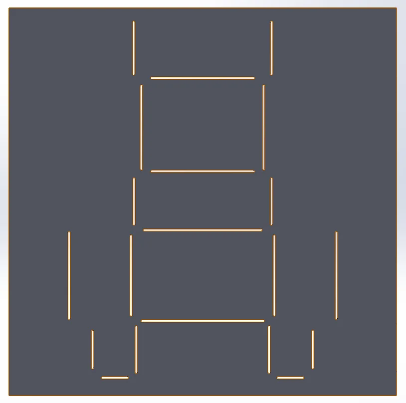
The template is used to score the bending lines of the box before folding
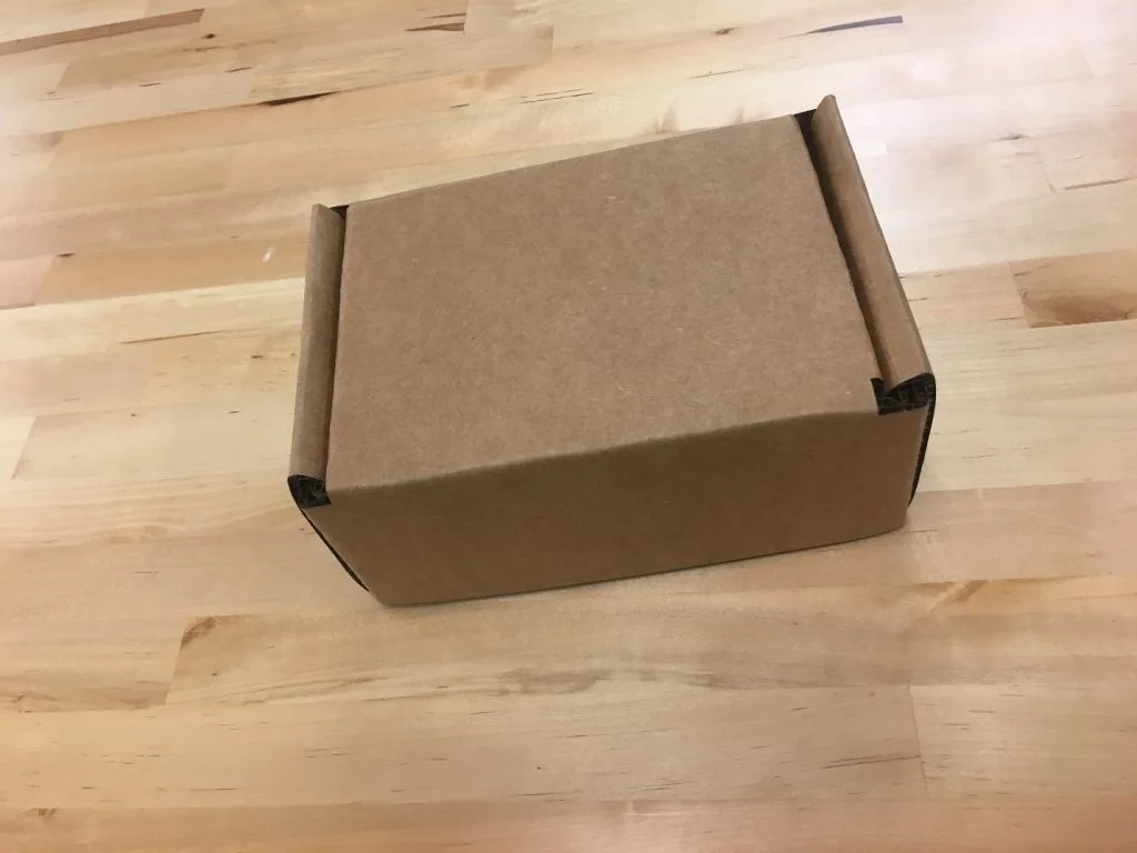
Once the box has been folded, the contents can be placed inside of it and only the lid needs to taped shut.
In my experience, SOLIDWORKS Sheet Metal is a useful and easy to use tool that interfaces well with a variety of other machines and software. When transitioning from designing to manufacturing the box, I appreciated the save as DXF functionality of SOLIDWORKS. For me, it makes the transition from flattened part to DXF quick and simple. A DXF is a versatile file format which I have been able to use to control a variety of machines, such as laser cutters, water jets, or CNC routers. I would recommend SOLIDWORKS Sheet Metal to anyone looking to design a box, housing, or enclosure.