Best Practices for Solving Large Assemblies in SOLIDWORKS Simulation


Did you attend this year’s 3DEXPERIENCE World 2021 event with almost 38,000 attendees? Were you able to watch over 130 breakout sessions in three days?
If your answer is no to any of these questions, no worries! The live event is over but replays are available and can be found on the 3DEXPERIENCE World 2021 website. Go to the agenda tab in the top navigation. If you haven’t registered for the event, registration takes less than a minute.
Among the hundreds of On-Demand Sessions, you will find our SOLIDWORKS Simulation team’s presentation on the Best Practices for Solving Large Assemblies. In less than 30 minutes, Nandish and I provided session attendees with 20 tips and tricks on how to tackle structural analysis problems on large assemblies like a Pro.
So, if you have ever struggled with meshing, instabilities, interferences, gaps, long solve time, etc., this session is for you. It covers the latest enhancements that make defining contact, meshing and solving easier than ever before. I can’t cover the whole presentation in this blog, here is a little taste to whet your appetite to watch the full session.
Geometry preparation
To prepare your large assembly geometry for simulation, we recommend that you isolate and analyze critical sub-assemblies. A best practice is to simulate the worst case scenario.

One of the great benefits of CAD-embedded simulation is the tight integration between CAD and Simulation. When using a SOLIDWORKS configuration for Simulation, you can make modifications for simulation (component simplification or suppression) and not affect the production model.
Meshing
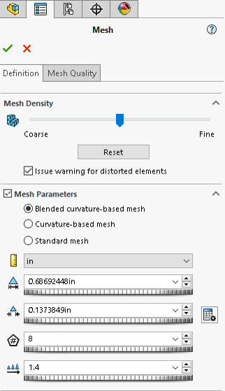
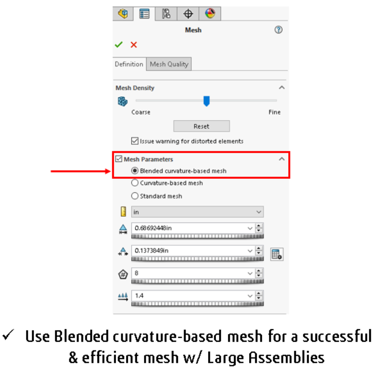
Some of our users may not know that we have 3 different meshers, so the obvious question is when to use which one? The default is the Standard mesher but, you might want to consider switching to the Blended Curvature-Based mesher (also called BCB) and to a lesser extend the Curvature-Based mesher (also called CB) for large assemblies. In the past, you probably didn’t use BCB either because you didn’t know it existed or because it was too slow. Now, with the 2021 release, BCB is significantly faster and much more robust. It also uses multithreading and parallel multicore processing to more quickly mesh large assemblies.
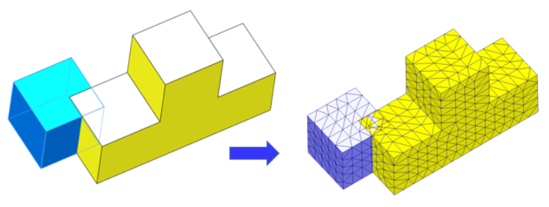
The Standard mesher uses a constant Global element mesh size to put uniform mesh across parts. In some cases, it could mesh over small features using this tolerance value. The newer BCB and CB meshers have a Maximum and a Minimum element size. These meshers will use this element size range to put large elements on wide planar areas and small elements on small features. As a result, you will get a more efficient use of elements and nodes. What I have found many times, is that I am able to get a successful mesh with the BCB mesher in cases where the Standard mesher failed.
So I recommend you try Blended Curvature-Based mesher for large assemblies.
Interferences
A common problem you may encounter is that your assembly may have lots of interferences. Not all interferences are the same, let’s break down the interferences into three scenarios.
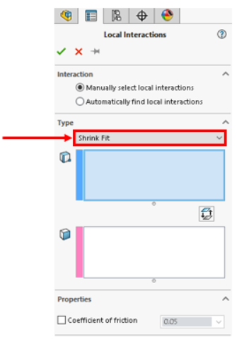
The first scenario is Shrink Fit, a technique in which interference fit is achieved by a relative size change after assembly. This is usually achieved by heating or cooling one component before assembly and allowing it to return to ambient temperature after assembly. Shrink Fit typically employs thermal expansion to make a joint. If you want to calculate the results of this interference scenario, you will need to specify the Shrink Fit interaction type between the interfering components.
The second scenario is when the Interferences are not present in key components. You don’t need the software to calculate the interactions between these components and you just want quick results. In this case, you don’t need to do anything, simply use independent mesh which is the default setting starting with SOLIDWORKS Simulation 2020. By using this setting, the software will mesh each component independently.
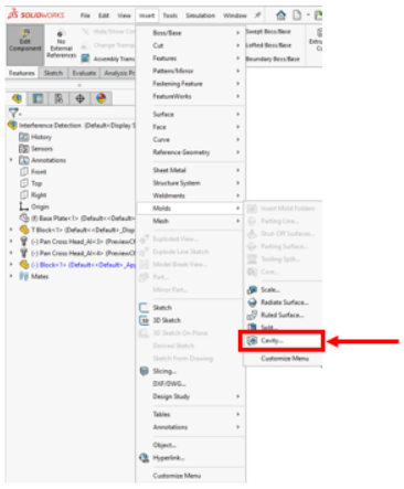
The third scenario is where interferences are present in critical areas and you want to resolve them by applying a Boolean operation. The tool to use is the Cavity tool under Insert>Mold. To remove the interference, edit the part you want to cut within the assembly, then select the Cavity tool, choose the part you want to use as cutting tool and the other as part to be cut.
Gaps
Gaps can be seen in the same light as interferences. In the case of gaps, they don’t cause the mesher to fail, but the solver is unable to complete. This is because the presence of gaps in your assemblies can lead to structural instabilities. The first challenge is to find any gaps, because often it is difficult to ‘see’ the presence of gaps in your model. Handling gaps is much easier in 2021 because SOLIDWORKS Simulation has introduced 3 new parameters to help you overcome gaps in your models:
- The gap range for bonding treats components as bonded together by ignoring the specified gap
- The gap range to consider contact specifies a gap range to establish contact between the non-touching bodies which have gaps between each other
- Contact stabilization adds a small numerical stiffness to the qualified regions to resolve instability issues encountered at the start of the solution before the contact is established.
-

Figure 6. 3 new parameters introduced in SOLIDWORKS Simulation 2021 to handle instabilities due to gap
In this blog I have given some of my favorite Tips and Tricks from our presentation at 3DEXPERIENCE World 2021. To get more time-saving tips and Best Practices for solving Large Assemblies, I would encourage you to watch the full presentation our On Demand presentation session (video below) and download the presentation PDF at 3DEXPERIENCE World 2021. But you better act fast because after April 2nd you’ll only be able to find the sessions on YouTube!