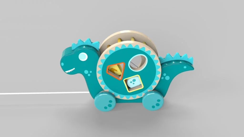
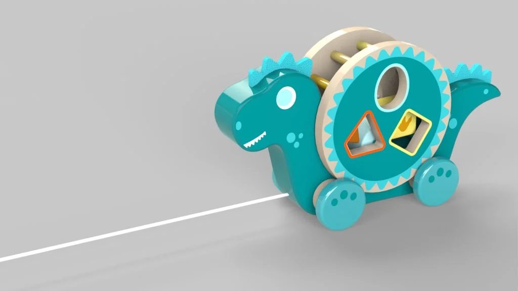
For this tutorial I wanted to play around with a toy design that used movement of one part to move other parts. So, I designed this Dinosaur Pull Along toy, which when pulled along a surface, the wheels turn causing the shape sorting barrel sat on inner wheels to rotate backwards. The barrel is removable from the toy but will sit in place on the wheels. It also contains 3 shape blocks which also move around within the barrel as it turns. I have seen several of these fun toys around and decided to create my own. The files needed for the tutorial are available here. You will find the blocks and floor parts needed for the analysis part of the tutorial, along with the DXF files and decals for this design.
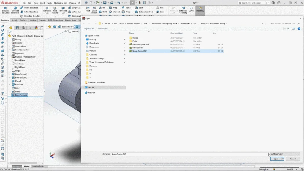
The Dinosaur Pull Along toy is created as one part, I find it easiest to work this way and create a multi body part for exporting into separate parts for assembly. So, the design of the toy is pretty simple, and is built up of several DXF files which have been designed to import into SOLIDWORKS in precise locations. You can ensure this happens when you create your own DXF files by layering your sketches where you want them in your vector software and exporting them in place one by one. That way they will come into Solidworks where you want them to be.
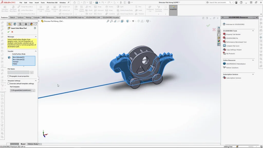
With the fully modelled toy done, groups of solid bodies were exported into new parts. In this case the model was split into 3 parts, the dinosaur, the shape sorting barrel and a set of wheels. With them all saved separately they could be brought into an assembly.
It is important in the assembly to start by adding the floor part first as without this you would not be able to run the motion analysis, the wheels need a floor part to move along. All the other parts were assembled and mated into place. It is important to note that the mates added were not just for positioning but also to keep all parts together so that I could change the position of the toy as a whole. However, once we begin the motion analysis, all the mates apart from those ensuring the toys stays in a straight line are suppressed. If they were not suppressed, they would cause the analysis to error as there would be too many controls, and for a motion analysis, we rely on the contacts, gravity and force to control the individual parts in the assembly.
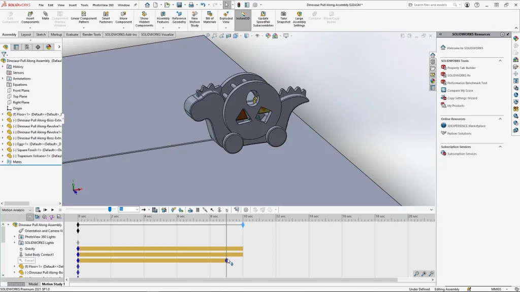
The analysis is fairly simple in that it only needed to have gravity, contacts on all parts, and a force on the string to pull it along. The force is turned off in the analysis before it ends so that the toy comes to a standstill. You will see this at the end of the tutorial.
Once the analysis was complete, I re-saved my assembly. It is than up to you if you would like to add any appearances and decals to your model. The decals are available in the file download. I went back through all the individual parts of the assembly and added any appearances and decals and resaved each one. That way when I went back to my assembly, you can see all the decals applied. Below is another rendered image of the final toy design produced with SOLIDWORKS visualize.