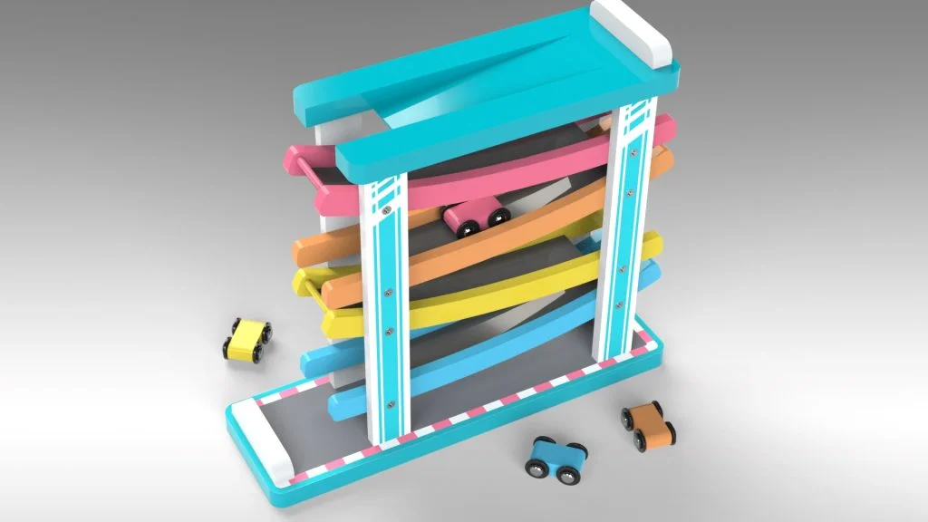

I have seen many variations of these car racers recently, and even bought one for family. I find them quite interesting to watch the little car go down the tracks flipping over as it goes. I’m not sure how long they would’ve entertained me as a child, but I think they are a novelty toy all the same. To follow this tutorial you will need to download this file here. Within this file you will find the DXF file needed for the front panels. The DXF file was created in a vector program called CorelDraw to map out where the screw holes would go for the car ramps. There is the screw part which is inserted into Car Racer Track front panels to hold the ramps in place. This is just as an example for the construction of the toy, there would be more screws needed to construct this design. Then there is the four colored cars parts, and a set of wheels that are all assembled together at the end of the tutorial. Finally there are two decals which you can add to the car racer if you wish to, I added these to the front and back panels, and the base panel.
The DXF file I imported for the front panels already had the screw holes added to it, however sometimes you will find when you export a circular profile from a vector program your circular profiles come in without a center point to use as a guide. Because of this, I had to convert all the circles in the sketch for construction and draw new circles in SOLIDWORKS and manually move it into place with move entities. The circles where then used with hole wizard to create custom countersink holes for the screws to be added later on.
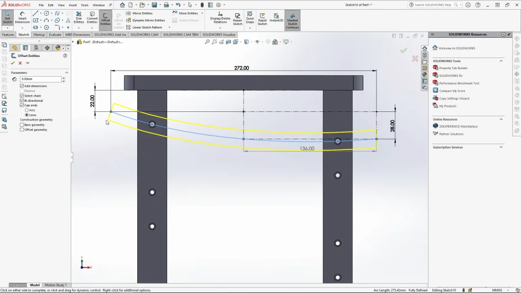
For this tutorial the most useful tool was the offset entities sketch tool. it was used in several steps of the tutorial. I used it to create the ramp sides by sketching out a spline, and offsetting it bi-directional (both ways) but also capping the ends to close off the offset into a profile. Here you can choose to cap the ends with either an arc or line. For this shape I chose line, and then added a small fillet to the corners afterwards. The offset entities was also used to create the ramp itself, by offsetting the side profiles and then offsetting that entity in one direction and capping off the ends with lines. The sketch could then be extruded to create the ramp.
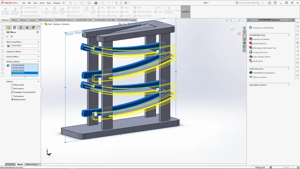
Mirror Bodies came in handy too for this design, it was used to mirror over the front panels, but also to mirror over the ramp sides. I always like to start my models center to the parts axis so that you have the front and right plane center to the model. In this case I started the base of the model from the center of the axis on the top plane. This meant that i could use the mirror bodies feature straight off the front plane without the need for a new plane. The feature was also used for mirroring over all the screw parts from the front side to the back panels too. This tool always saves me so much time.
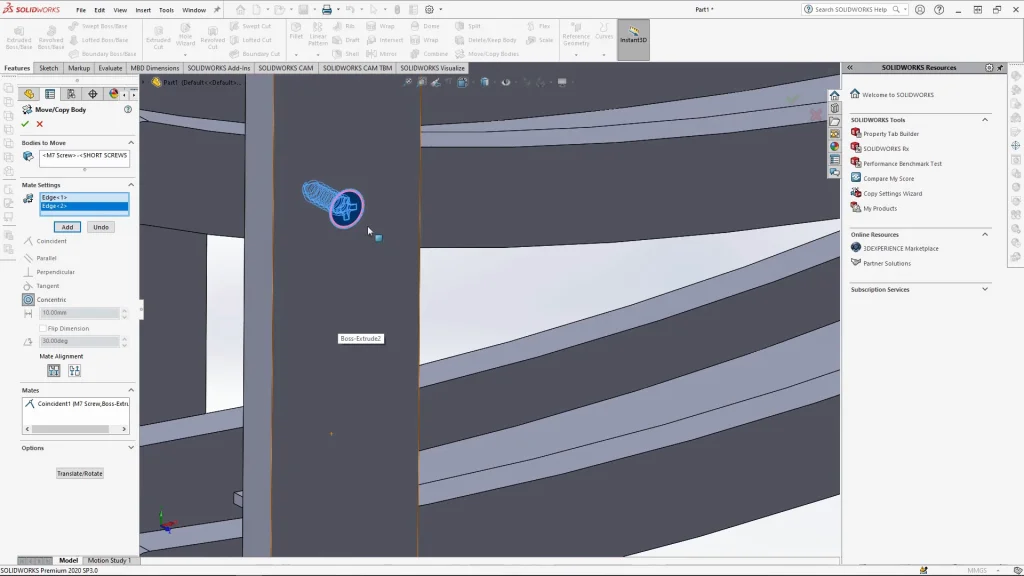
The screws are added using insert part, they are then mated into place using move/copy bodies. There is a constraints option within here that allows you to mate the parts into place like you would in an assembly. The only differences are that the part you bring in cant move around by dragging it, and you have to mate each part individually.
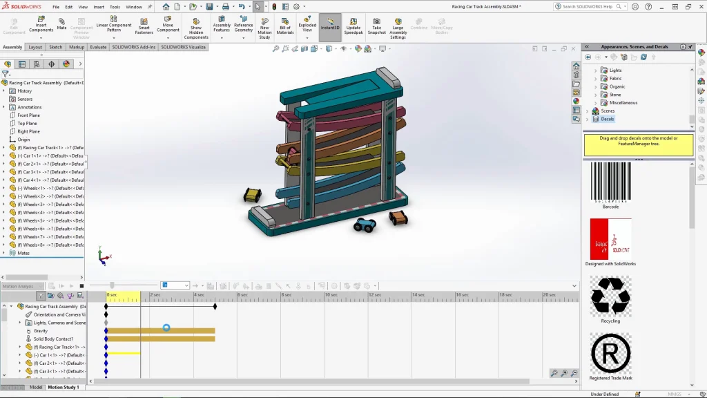
Once you have completed the cars racing track part, you will start creating an assembly, the race track goes in first, then you can bring in the individual car parts into the assembly dropping them near the tracks. For this tutorial I have only showcased one car going down the track, but you could line them up on the starting ramp to see how they all fall during the motion analysis. The wheels are mated onto each car with concentric and coincident mates, and the car that is on the ramp has additional tangent mates attaching it to the ramp floor. I also added a parallel mate to the side of the car to the ramp sides for positioning the car in place. Both the tangent mates and the parallel mate were suppressed for the analysis. Gravity, and contacts were added to the analysis before it was run, this finished rendered result can be seen at the end of the tutorial.