

The intention of this article is to describe a portion of the process required to engineer a frame and engine mounting system for a single engine aircraft.
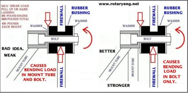
Figure 1: Many Design Options are available. For example, the above image depicts two options for mounting to the firewall.
The mounting system is the primary interface between the powertrain and the frame. Therefore, it is vital to determine the vibration isolation characteristics. Many mounts are available to isolate these frequencies. However, for this project, my client chose an elastomeric mount. This is primarily a rubber mount that can withstand large amounts of deformation under load with the ability to almost retain its original shape when the load is removed. Rubber is a viscoelastic material which enables it to be used as an isolator and as a damper with excellent results. Rubber engine mounts can be implemented through a passive system, or an active system with a control loop adjusting stiffness based on sensor input to the computer. Many times, these are used in conjunction with one another to provide design redundancy.
Requirements:
- Determine force isolation, often encountered in rotating or reciprocating machinery with unbalanced masses.
- Determine motion isolation……minimize the transmitted vibration amplitude so the mounted equipment is shielded from vibrations coming from the supporting structure.
- Ensure the natural frequency of the air-frame and support equipment is lower than that produced by the power plant.
Goal:
Achieve low vibration transmission to the airplane structure and occupants.
Mechanical System Considerations:
As engineers, we are constantly weighting out design options. For this challenge, mount stiffness must be as low as possible. However, this causes increased static deflection. Also, handling and maneuverability are enhanced with higher stiffness, lower dampened engine mounts.
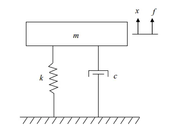
Figure 2: Mech Model for Elastomeric Engine Mounts
Modeling Setup:
Six DOF to be excited due to inertial forces and torque produced by the main crankshaft.
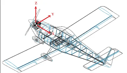
Figure 3: Engine 6 DOF
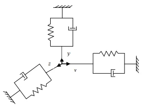
Figure 4: Spring dampener on each axis
Supporting Theory:
Utilizing Voigt’s & Maxwell’s Model we can accurately depict the system.
- The model consists of a single degree of freedom system where the spring and damper are represented by the stiffness ??1 and damping coefficient ??1 (See figure 4). The snubbing effect is considered by adding an additional two linear springs ??2 and ??3 that will be engaged when the displacement amplitude ?? of the isolated mass exceeds the snubbing gap ???? (See figure 5).
2. The equations of motion for the model are as follows:
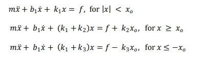
?? represents the mass of the isolated system and ?? is the excitation force acting on the system.
3. Completed Voight/Maxwell Model:
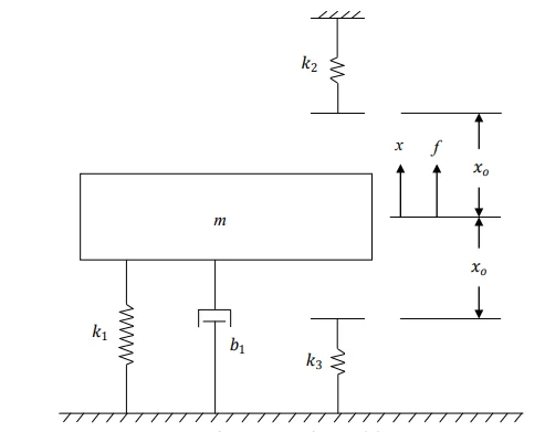
Figure 5: Voight model-Minus Snubbing effect damping.
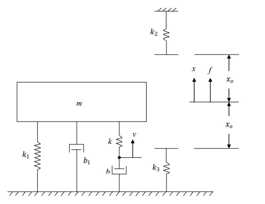
Figure 5: Maxwell-Voight Model with Snubbing effect
Additional Considerations:
The ol’ adage “garbage in, garbage out” certainly applies to this case study. Capturing and defining accurate load conditions can prove to be the biggest challenge of all, as is the case of many simulation studies (See figure 6). The load cases are extremely dynamic on an airplane. Through each phase of flight (Taxi, Takeoff, Cruise, Landing), conditions are constantly being modified. Then there’s environmental considerations. Analogous to an unbalanced spinning wheel, g-loading in “chop” (turbulence) can create conditions known as “Whirl Mode”, in which the application of a gyroscopic moment to the powerplant provides an excitation of a bending resonant frequency of the powerplant / mount system.
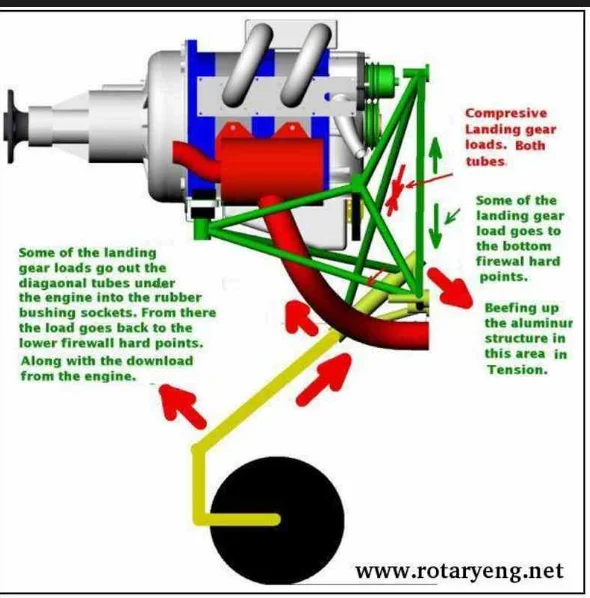
Figure 6: Load case during touchdown
To properly model this will require multiple studies using several specific FEA studies. For this article, I chose the most common engineering requirement…Natural Frequency Analysis.
Static Modal Results/Setup: (Figures 7,8,9,10,11)
-Study Type:
Natural Frequency response study.
-Excitation Frequency
Engine at idle RPM’s
-Load Case
Standard g-loading acceleration applied.
-Software
SOLIDWORKS Premium and Simulation Professional.
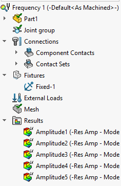
Figure 7: Study Setup
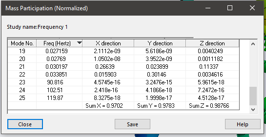
Figure 8: Confirm Mass Participation- Use this to qualify results.
May require many modes. 80% mass participation if optimal.
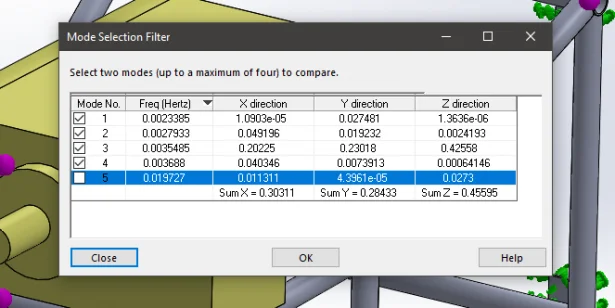
Figure 9: SOLIDWORKS Mode Compare-Helps identify Axis of oscillation.
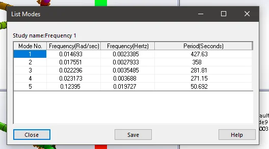
Figure 10: List Modes to identify Natural Freq- 427.63htz was my first natural frequency.
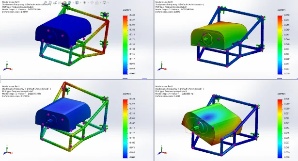
Figure 11: Mode Compare Visual
In conclusion, SOLIDWORKS Simulation was able to successfully replicate multiple load cases, similar to different conditions the aircraft is likely to receive on a normal flight. My client was also able to capture natural frequency modes, and adjust geometry, or materials accordingly to avoid these ranges of frequencies.
By: Rob Stoklosa • SOLIDWORKS Application Engineer • TPM