
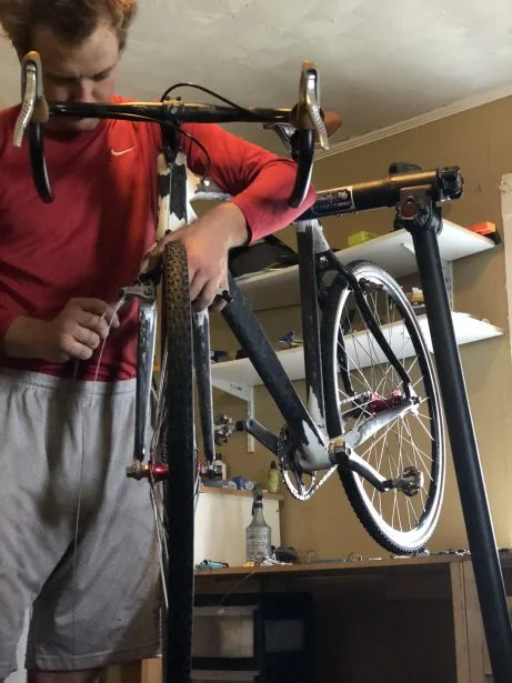
For the upcoming cyclocross (a cycling discipline) race season, I wanted a new bike. I found a great deal on one, but needed to modify it for my “needs.” In particular, I needed a new set of dropouts. What is a dropout you ask? Because surely in the bike world it’s not the same thing as your buddy from freshman year who is now a CEO without a degree. In the bike world, it’s what holds the wheels to frame or fork.
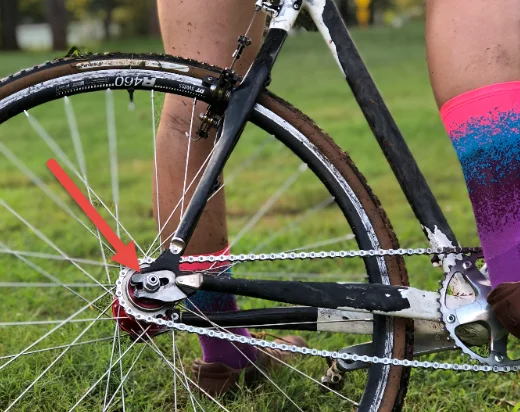
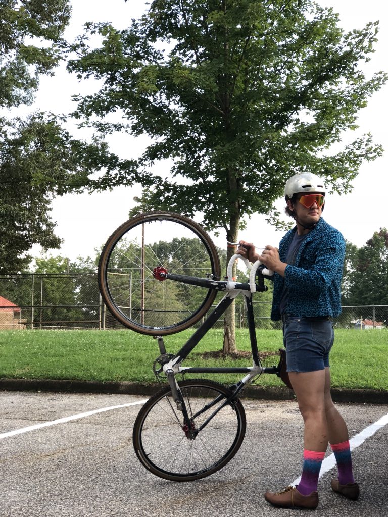
This is a dropout. Being ridden by someone who was almost a dropout.
The frame that I have already has dropouts, so why create new ones? Good question. For the single speed life, is why. Single speeds are lighter, simpler, more fun, and just more rad. Because single speeds don’t have derailleurs, which change gears and tension the chain, I need a way to tension the chain. Instead of the existing “vertical” dropouts, I want “horizontal” dropouts for quick and easy tensioning. Spaced right, a new set of dropouts will also allow me to use my race wheels from the track instead of investing in new wheels. Here we go.
Basic Modeling
While the part is fairly simple, it is important that I get three things right:
- Bolt pattern
- Wheel Spacing
- Axle spacing
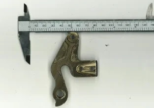
To start, I used one of my favorite sketch tools-Sketch Picture. As much as I like my calipers, I’d much prefer to figure out that bolt pattern with a good picture instead of measuring, typing, checking and repeating. Sketch Picture allowed me to take a picture and bring it into a SOLIDWORKS sketch, scale it, and then trace it. So, I scanned the current dropouts (it can be helpful to put a measurement tool in the picture)…
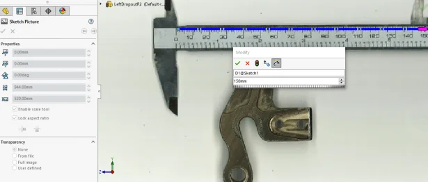
…fired up the Sketch Picture Tool within a sketch inside SOLIDWORKS…
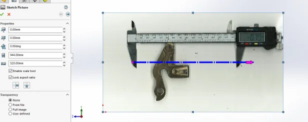
…and then used the scale tool to get the size correct. This works by dragging the blue line around. Once you drop the end point with the purple arrow, a dialogue box pops asking you what the dimension of the line should be. I used the calipers in the background as a reference.
A little bit of rotating, dragging, rotating and flipping later, and I was ready to trace. A helpful tip here is to leave the Sketch Picture in a separate sketch.
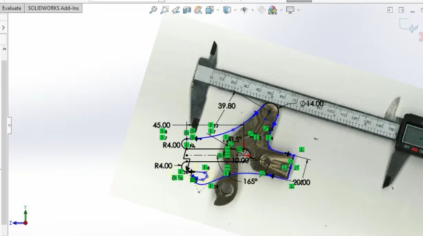
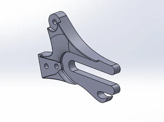
And bam, I’m ready to create my 3D geometry. It wasn’t quite as simple as a single boss extrude as I wanted the wheel spacing to be different and therefore, the dropouts had to be offset towards the center of the bike. But it wasn’t a problem, and I was off with the first version.
So now we just send it off to be CNC’d, right? Well, considering the quote I got for the set was $362.89, and I have access to both a HP Jet Fusion and a Markforged X7, I decided to go a different route. The Markforged X7 can lay down carbon fiber as part of the print, claiming to be end-use ready. Time to put that claim to the challenge. But before I get ahead of myself, a test fit.
Initial 3D printing
With the first iteration of the model, I wanted to do a cheap 3D print job for test fit purposes. Cris was getting ready to do a run on the HP, so I threw a set into that build. I came back the next day, and boom. Total Cost: $9.35.
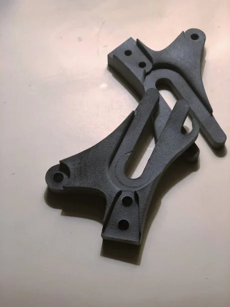
Test fitting them that evening showed one bolt hole was off by ~.4mm and the interface between the frame and the dropout itself wasn’t great. Not to mention that hook didn’t quite do what it was supposed to. A quick fix, and another print, but this time on the Markforged X7, as there weren’t any HP builds happening. While the X7 has the capability to print carbon fiber, and that is what I was shooting for, this second iteration was done just in Onyx, a material based on Nylon with chopped carbon fiber, which is much cheaper than laying continuous carbon fiber. Total cost: $6.51. The second iteration fit well and I was ready to go on to the final.
Let’s be smart about this-Simulation
Up to this point, I hadn’t really worried about strength. Just put a lot of carbon fiber into the final print and it will all be fine, right? That’s what I was thinking when I was getting ready to hit the print button and then thought “Wait a second, I have SOLIDWORKS Simulation. I’m an engineer. I can do better.”
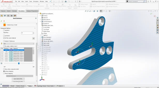
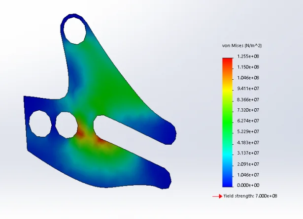
And so off to better with SOLIDWORKS Simulation. Before trying to figure out the best orientation of the fibers, I just wanted to see if I could improve the shape. So I applied an isotropic (same material properties in all directions) similar to the Markforged carbon fiber and defined my fixtures (the 3 bolt holes). I then made a worst-case scenario with the axle bolts at the end of the slot and applied my loads (250N on either side of the bolt, 320N, or half body weight, down). Finally, I meshed (curvature based with a max element size of 3.6mm) and ran. First thought: Good thing I didn’t just hit print.
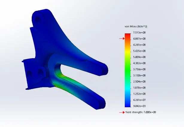
Stress Results 1: Failure.
Adding material directly below the start of the slot helped, but still didn’t bring it do a comfortable point.
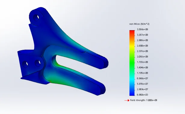
Stress Results 2.
So, I shortened the length of the slot. This effectively restricts my gear options (before I have to change a chain), but lessens the stress of the worst-case scenario. I also thickened the slot by 1mm.
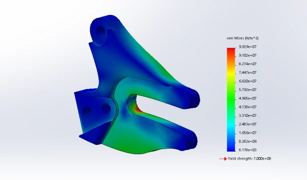
Stress Results 3.
Satisfied with the shape, I went on to figuring out carbon fiber orientations.
What about that carbon fiber?
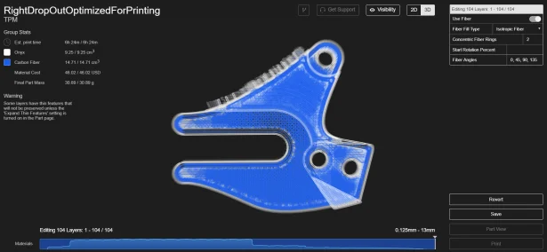
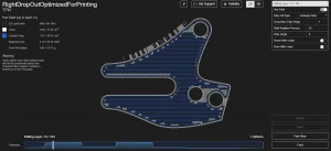
Where there’s an opportunity to specify, there’s an opportunity to optimize. With Markforged’s Eiger slicing software, we can specify not only things like fill density and wall/roof/floor layers, but also fiber direction for each layer. In this case, there were 104 layers. The obsessive side of me quickly starting driving all the other sides of me crazy.
So what to do? One could just add as much carbon fiber in there as possible and hope for the best. That starts getting expensive, ($46.02), and we don’t even know if that cost is helping us.
Eiger 1: Should we just max the amount of carbon fiber?
Enter SOLIDWORKS Simulation. Within Premium, I was able to define a shell face, enter orthotropic material properties based off of Markforged’s carbon fiber properties, and then play around with fiber angles. While this seems like it’d be a good idea for a Design Study, if you set the step size of each layer to 15 degrees from 0 to 180 degrees from horizontal, just 3 layers gets you 1,728 iterations. For 100? SolidWorks says no. Instead, I edited each layer’s angle in the shell definition. Initially I defined it as 48 layers of only 0-degree fibers (horizontal).
I then “systematically” played with the orientation at each layer. Of course, with the Onyx and the concentric fibers, there is either a lot of set-up work or the results have to be taken with a grain of salt. I chose the grains of salt.
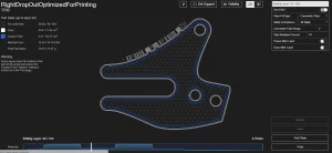
With cost and strength both of concern, I ended up with an I-beam of sorts: Lots of 0 degree and low-value angles on either side of the dropout with just concentric fibers in the middle. In Eiger, this looks something like this:
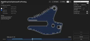
And Sim results something like this.
Mostly satisfied, it was then time to hit print.
Putting it all together
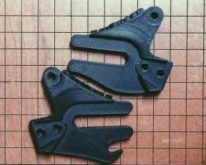
The prints came out quite well.
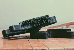
Lettering? Because I can.
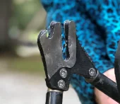
The only downside to horizontal dropouts is the axle bolts need to be tightened to kingdom come to prevent sliding forward under power. To prevent marring of the dropouts, I scheduled a coffee date with my favorite tool, the Dremel, and a few hours later, I had some stainless steel plating. Add some bolts, and we were in business.
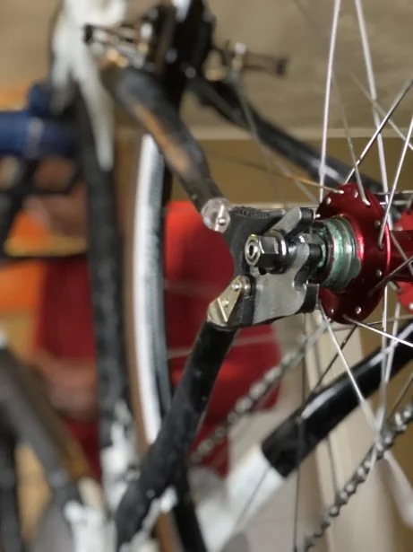
From there, I built the rest of the bike up, and it was time to test!
Testing
Without a fancy test lab, I was left to do all testing live, with myself as the test dummy. Before starting, I needed proper test dummy apparel.

That ought to work.
With proper test gear on, it was time to start. Riding around on it felt fine, so I jumped to something a bit more taxing-The bunny hop. This is a pretty common move in cyclocross racing, so a good starting point to put the dropouts to the test.
That worked just fine, so I decided to go to the next level-the stairs. While running up stairs is sometimes required, riding down is never part of a race course. But I wanted to be thorough…
Stairs? No problem. There was yet one tougher test to put the dropouts through-the drop. I had some doubts, both on the dropouts and my skills. But sometime you just have to full send it and see what happens.
What happened? Well, both myself and the dropouts rolled away in tact, and rather stoked at that. Without anything bigger that I wanted to go hit, I rode away and called it a success…mostly.
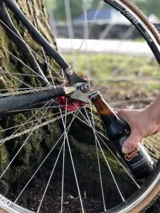
To prevent the axle from sliding forward, I had to tighten the daylights out of the axle nuts. This ended up pinching the steel plates. I also assumed this would crush the 3D printed structure as well. After testing, I pulled the wheel out to get a closer look.
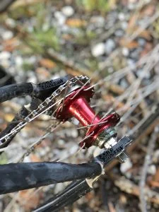
To my astonishment, there was only a slight indent in the 3D printed part itself. The tightening had warped and pulled away the metal piece, but that’s an easy fix-a hammer to flatten and JB Weld to re-attach.
With that, there was yet one more test. And that one too, was a success.
Cheers, SOLIDWORKS, cheers indeed.
By: Luke Woodard • Application Engineer • TPM