
SOLIDWORKS Simulation
When simulating large, thin objects it is much more simple, computationally, to define these types of objects as shell elements rather than solid elements. The problem is that most beginner simulation users are not comfortable with this element type because they do not know how to define a shell element mesh or how to connect it to the rest of the parts in the analysis once it is defined. In this post, I will show you how to define a shell element using the Shell Definition tool and then how to define Loads, Mesh Controls, Fixtures, and Contact Sets to that shell element once it has been defined. Lastly, we will briefly go over what a fully meshed shell element mesh looks like.
How to define a Shell Element Manually
First, find a part that is large in one plain, but comparatively thin through its thickness. For example, a sheet metal piece. The bracket you see below is an example of this sort of geometry.
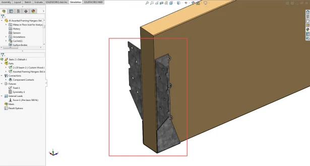
Next, click on the object in the graphics window to see it highlighted in the simulation tree.

After right clicking on the part file in the simulation tree, you will see the Define Shell by Selected Faces command in the popup window.
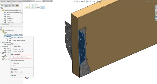
After clicking on this tool next click on the faces of the large thin object that you wish to treat as a shell element mesh instead of a solid element mesh. Now set the shell thickness to the actual thickness of the object.
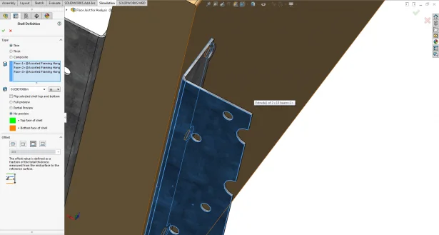
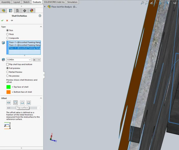
Lastly, make sure that the offset parameter is correct based on the face that was used to define the shell element. In the image below, the top surface choice has been selected and this puts the offset that the Simulation program uses to calculate the stresses and displacements through the sheet metal part in the opposite direction then it actually is.
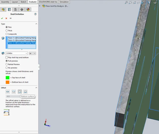
In the image you see below, the Bottom Surface Offset option has been selected and can be seen to be the correct direction to cover the thickness of this sheet metal part. It should be observed that a green side is on one side of the thickness and an orange side is on the other side of the thickness.
Now that you have defined a shell by its selected face, make sure that you use that same face or faces when defining the studies Loads, Mesh Controls, Fixtures, and Contact Sets. Otherwise, the program will not know what you mean and will throw errors when the study is running and will fail to finish.
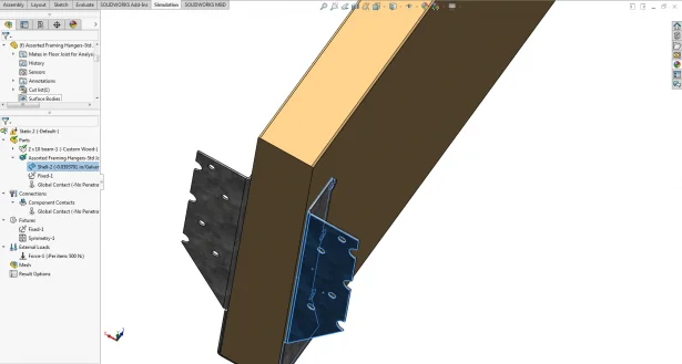
If the Simulation study has a lot of shell elements in it, it can be very difficult to remember which faces were used to define the shell element to use to apply Loads, Mesh Controls, Fixtures, and Contact Sets. An easy way to visually see the selected faces that define a shell element is to click on the object in the graphics window to see it highlighted in the simulation tree. Then expand the shell manager folder to view all of the shell definitions for the part below it. Now, just click on the shell definition of interest and the faces that were used to define the shell element will be highlighted in blue as you can see below.
Now, simply apply the conditions that you wish to apply to this highlighted face. After doing so, this shell element simulation part should be fully defined and you can move onto fully defining the next one.
What a fully meshed shell element mesh looks like
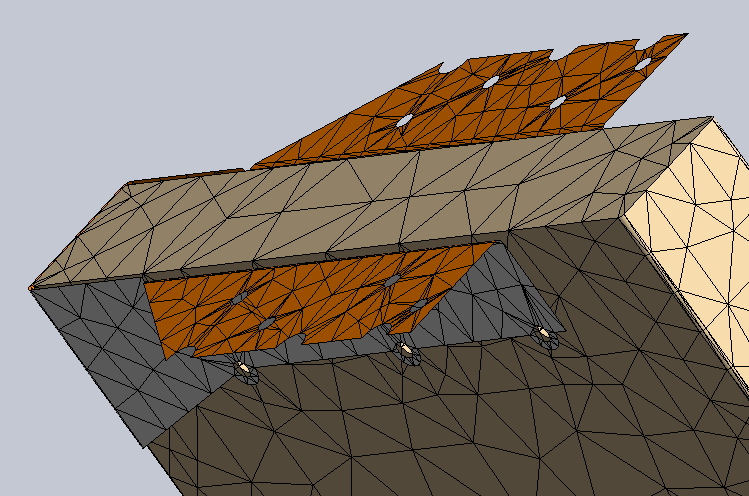
After the entire model has been set up properly in the simulation, it is now time to mesh. Shell elements have no thickness so be prepared for the geometry to look different than it did when it was a thin but solid part file.
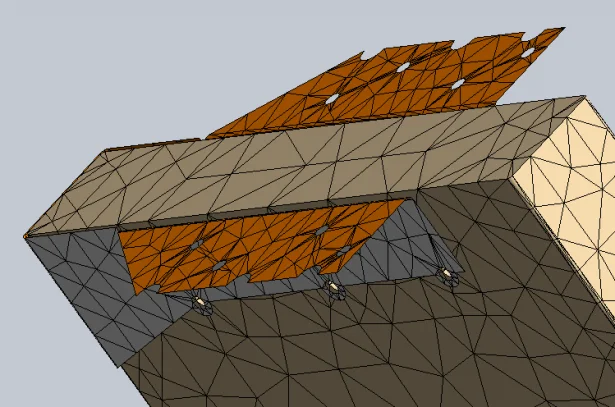
As can be seen in the screen shot above the meshed shell element is infinitely thin and shows a gap now between the shell part and solid part. This is to be expected and will not affect the analysis if the simulation was set up correctly. Because shell elements are infinitely thin, SOLIDWORKS Simulation uses a color coding system to distinguish one side of the shell element from the other. The Orange color corresponds to the bottom surface of the shell element while the gray corresponds to the top surface of the shell element.

Author: Taran Packer
Taran is a SOLIDWORKS Simulation Technical Support Specialist at GoEngineer. He has a Bachelor’s degree in Biomedical Engineering from the University of Utah. Taran enjoys learning about different tools in SOLIDWORKS Simulation, Flow Simulation, and Plastics.