
With any engineering project, the beginning stages include lots of brainstorming, prototyping, and trial and error. But ALSO – lots of fun and collaboration! The SOLIDWORKS Magic Wheelchair team ran through many iterations of ideas for Adrian’s Magic Wheelchair costume: a transforming dinosaur robot. Dan DeOreo presented the Transformer character Swoop to the team as a great design inspiration. Chinloo Lama created a proof-of-concept with a coffee stirrer, index card, pencil, and string, turning what a non-engineer would think of as “random office supplies” into a miniature wing prototype that could flap up and down.
Starting off, Dan knew that the arm needed to move in some way, and while a straight rotation of moving up and down would be much easier… it would not be as cool as multiple movements at once. And the SOLIDWORKS Magic Wheelchair Design Team never sacrifices cool for easy. To figure out the best way to create the mechanisms for the arm, Dan decided to jump into SOLIDWORKS xDesign.
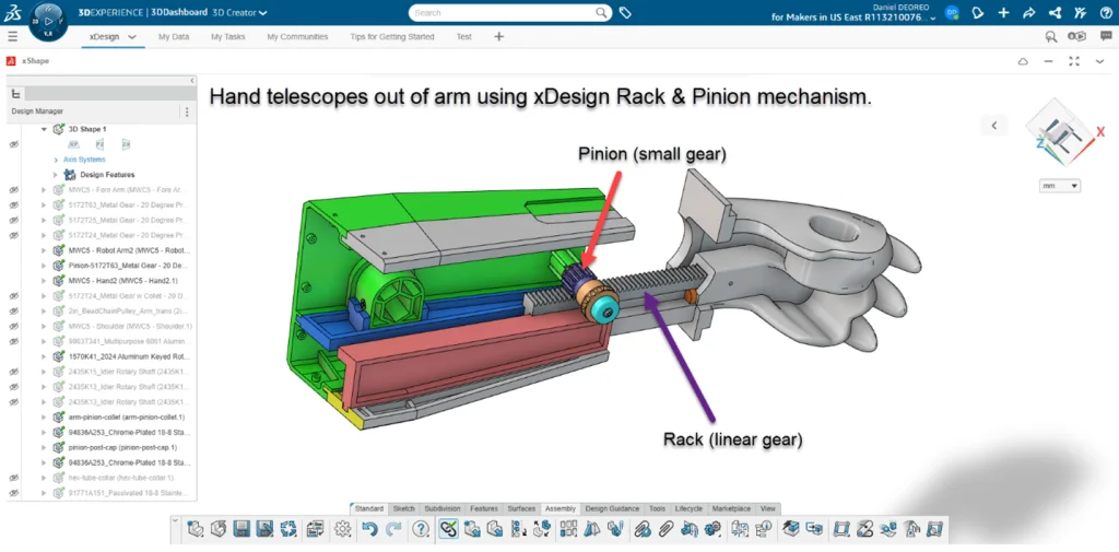
He started modeling all of the arm pieces and parts based on Albert’s design. After importing some gears he found on McMaster-Carr, Dan used the Gear command to animate them in xDesign. The gears turned the shoulder using a 5:1 ratio. He then used one of the driving gears from the shoulder to drive a rack and pinion at a 1:1 ratio so that the hand telescoped out of the arm while the shoulder and arm all rotated together!
Once the design was modeled and the mechanisms were properly animated in the software, the 3D printing began. Initially, the arms were way too bulky and heavy. Because of this, Dan had to go back and cut away a lot of the geometry. He roughed out the main arm parts as single components at first to get the mechanism working. He also had to break up the larger/heavier parts into multiple components, something very easy to do using the single modeling environment in xDesign.
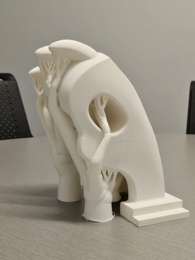
The hand was a project all in itself. It was the only component in the whole Magic Wheelchair build that was designed using subdivision modeling in xShape. Dan followed reference images online to create the hand shape, which took multiple design iterations. The first hand was heavy and sharp, but after some softening and refining, it began to appear like the model in the picture below. Lastly, he cored out large chunks of the hand on the inside to reduce the weight.
But now, how do you motorize Adrian’s arm and wing mechanisms? Yun Li took on the challenge. Similar to Dan’s background in designer experience, Yun Li is also a UX designer. She specifically works on the browser-based solution xMechatronics, which combines mechanical and electronic virtual solutions. She thought volunteering to take on the motor task would be a perfect way to help explore the workflow and challenges users face, while also building her understanding of mechatronics.
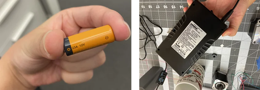
The main challenges that Yun Li overcame during the design process were figuring out the right motor and the right battery to use (after ordering a 12V battery and receiving a teeny tiny battery that wouldn’t be able to supply enough power). Yun Li laughed and said “I now know that it is important to read AND understand the data sheet.”
A quick SUPER cool tidbit: Yun Li took her experience and excitement of this build to the Mass Robotics Conference back in October of 2024. She presented to the audience how the SOLIDWORKS Magic Wheelchair Team used the xMechatronics software to create circuit schematics for the costume and plan the wiring layout to ensure proper functionality and organization.

The motor that Yun Li selected could generate only 1 foot-pound of torque. This created a new challenge for the team as the moving components of the costume (including a factor of safety) required 40 foot-pounds! Yun Li called upon fellow builder Sal Lama to help figure out a way to transfer the motor’s power to move all of that weight. The solution? A gear train.
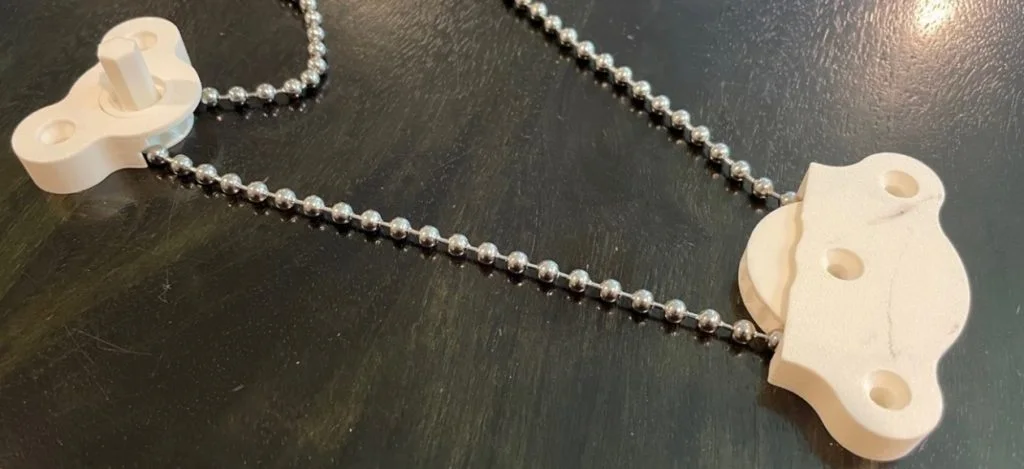
During the brainstorming process, Sal had to determine how to translate where the power was coming from (the motor and gear train) to where the power needed to be (the arms and the wings). Should they use a belt? Different types of gears? Rope? Cable? Sal ended up settling on a beaded chain, getting his inspiration from a type of pulley that opens and closes window blinds.
The biggest challenge in the creation of this gear train was figuring out the proper gear ratios to take the 1 foot-pound of torque that the motor could produce and transform that into 40 foot-pounds! This was made possible by one big gear …connected to one small gear …connected to another big gear …small gear long story short, lots of gears and lots of Sal’s mathematics that ended up creating a 40:1 gear ratio. This allowed the motor to provide all the power needed to make the costume transform!
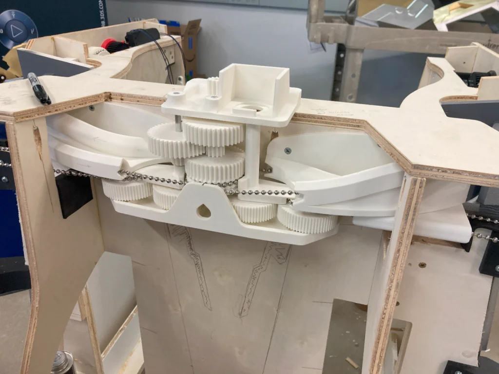
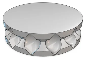
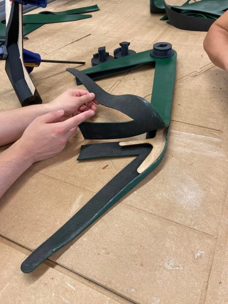
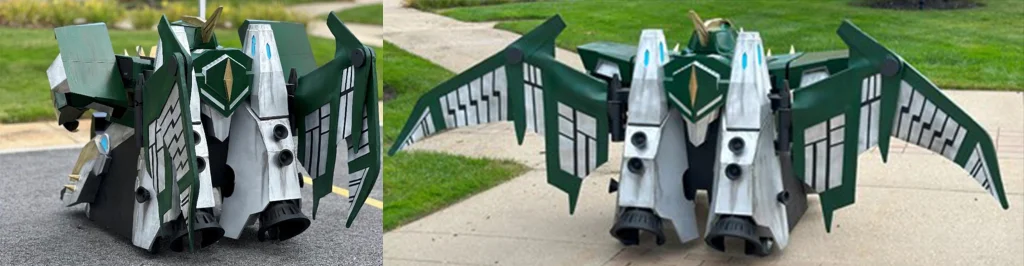
Now, let’s soar over to Chinloo Lama, the dedicated builder who took on Adrian’s wings. Chinloo and Sal devised a way to use the grooved, gear-type object shown below, much like a yo-yo. As the wings lowered, and with the help of gravity, the bead chain would unravel around the gear, “unwinding” the yo-yo. Then, when the stepper spun, the yo-yo would “wind up”, raising the wing tips to assume impressive full wing spans of 15 feet!
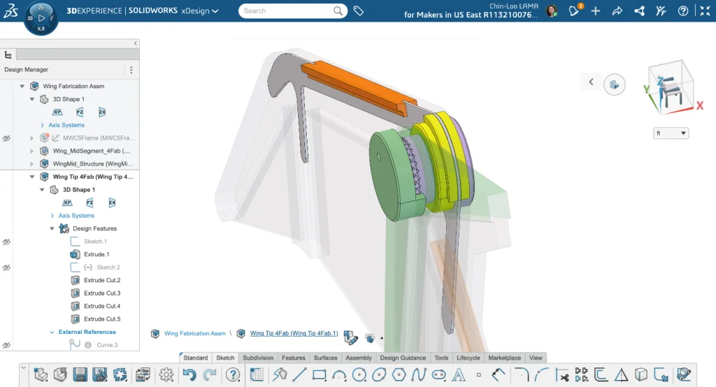
To convert the rotation motion of the bead gear into the lifting motion of the wing tip, Chinloo designed and 3D printed a multi-layer assembly of rotating components connected to a rib system that was cut out of plywood. This complicated junction exists at the “elbow” of the wing, housing all of the necessary components to make the wing mechanism work.
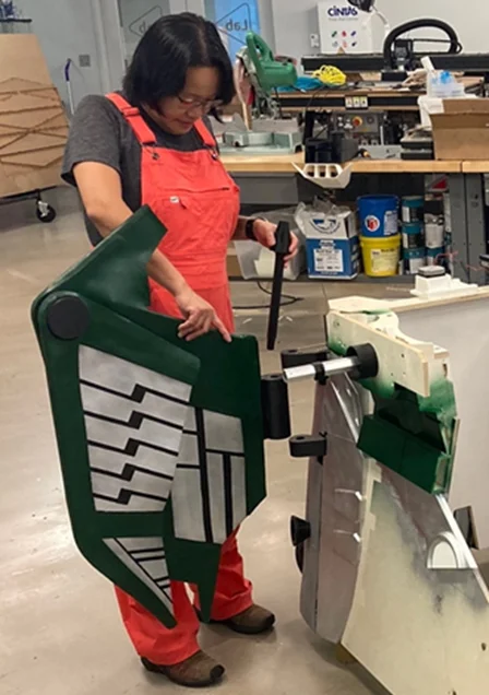
So is that it for the wing mechanism? NOPE. The wings have a dual-motion. This means that not only do they flap up and down, but they also tuck behind the costume’s back. Chinloo, with the help of the Magic Wheelchair build team, brainstormed this capability to allow Adrian the freedom to explore narrower spaces: fitting through doors, taking tight corners, all that good stuff. A hinge mechanism was utilized for this particular tucking motion. Think of a door hinge; all hinges operate the same way. They have separated cylindrical components that are united through a center pin.
Within the hinge area, Chinloo and Sal also cleverly included a channel from the motor to the wing for the bead chain to run through so it didn’t get pinched or caught in the movement. The channel allowed for the chain to travel at the same angle in which the wing was positioned.
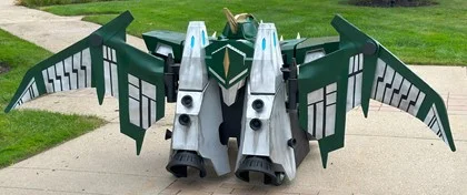
Zooming out and looking at the wings in their entirety, Chinloo’s extensive prototyping and designing allowed her to create this final lightweight solution that provided strength, flexibility and aesthetic results.
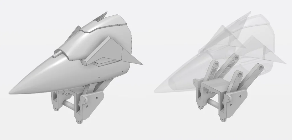
As for Albert Hernandez, he was the creator behind the beak mechanism. Originally, the team was going to have a button control all of the moving parts at once … however, they ended up using a lever to control the beak to make the costume more interactive for Adrian.
The main mechanism that allowed the beak to move was a 4-bar linkage. This is a specific mechanism that consists for four bars all connected at joints to move between two critical positions. In the costume, it was used as a lever to move the beak up to Adrian’s head and down to a resting vertical position on the chest.
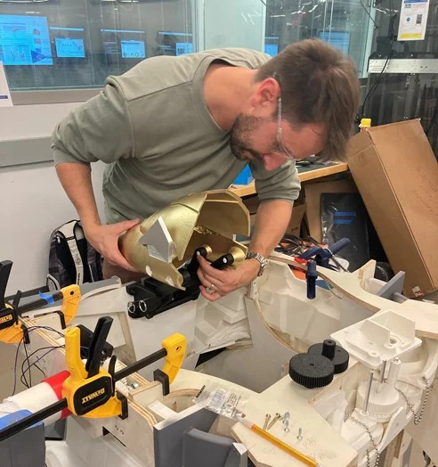
After Adrian excitedly shared how he has his own 3D printer and wants to be an engineer one day, the team made sure to utilize 3D printing as much as possible. And Albert made sure the beak was no exception. All of the beak’s components and pieces were 3D printed and then painted to look both prehistoric and robotic.
To conclude, I think the entire team can echo Sal’s sentiment that every member was an important contributor to the overall success of the project. Sal told me, “If we didn’t have Dan, there would be no arms. If we didn’t have Chinloo, there would be no wings.” The Magic Wheelchair experience truly shows how valuable and rewarding it is to work together as a team.
Does Magic Wheelchair sound like the kind of project you and your community would like to participate in? Get involved with Magic Wheelchair by starting your own team!