Model-Based Definition (MBD) is a journey. Defining product and manufacturing information (PMI) on 3D models rather than 2D drawings is just a start. After that, it’s vital to serve the downstream processes such as inspection, fabrication, and suppliers, in an organized, consumable and actionable fashion. Regardless of MBD or 2D drawings, the functional purpose is to communicate. Data authoring is only one side of the equation. Data consumption is another side that should drive how data is authored.
Let’s face it. Drawing has been perfected for over the last 20 years and sets a pretty high bar in engineering and manufacturing communications. MBD needs to catch up on both the authoring and consumption sides, which is why SOLIDWORKS MBD 2019 focuses on the following key aspects.
One frequent use case is sheet metal designs, widely used in computer enclosures, automotive, consumer electronics and so on. Drawing tools also added handy automations such as bend tables and bend notes a long time ago, therefore, many users have been asking for similar productivity tools in 3D. In the 2019 release, SOLIDWORKS MBD included the bend tables, bend notes and flattened 3D views as shown in Figure 1.
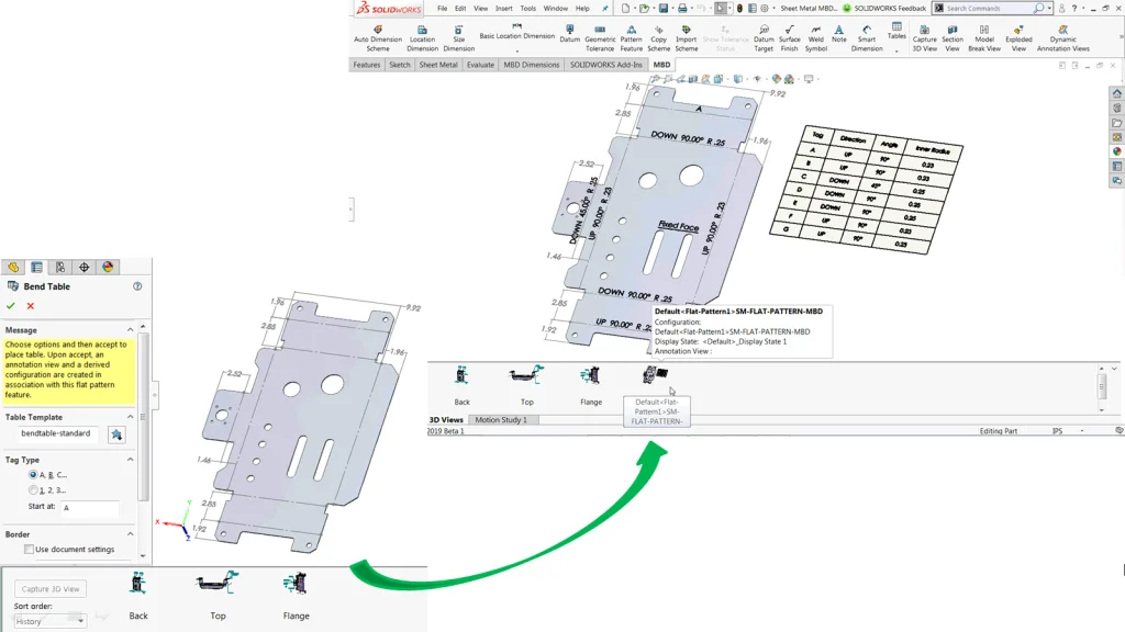
With an unfolded display as shown at the lower left corner, you can find Bend Table command under the Tables drop-down button on the MBD command bar. Upon inserting a bend table, you will find bend notes, such as directions, angles and fixed faces added automatically, matching the bend table. Of course, you can capture an unfolded 3D view to go back to this visual bookmark later. These additions fill a major gap between MBD and drawings, and will make the important sheet metal use cases more productive in 3D going forward.
By the way, you may notice the annotated bend distances. These are not part of the automation, but you can create dimensions between bend lines and flange edges pretty easily with Reference Dimensions, which behave similarly to 2D drawing dimensioning tools in that you can freely select geometric elements, such as sketch lines, edges, vertices, arcs, and circles. Defining bend lines is always important to communicate the exact offsets needed for press brakes on the shop floor. It has been traditionally conveyed on drawings. In 3D, Reference Dimensions can help.
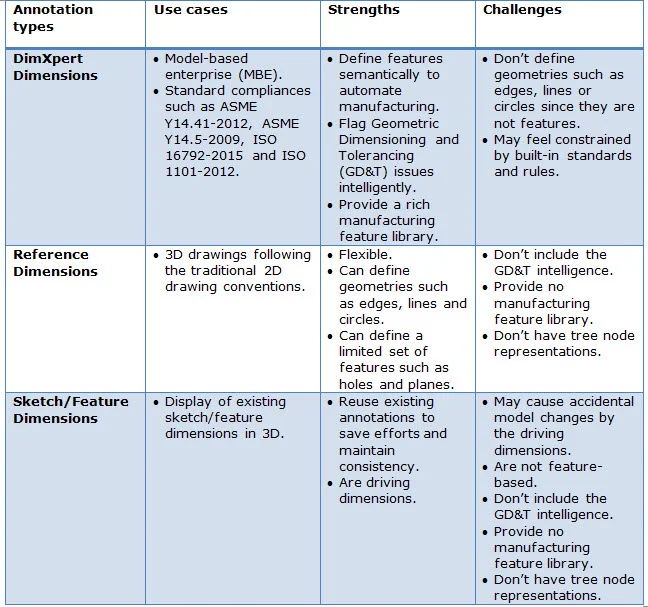
On the other hand, DimXpert is an annotation tool to define features such as holes, slots and notches, rather than geometries. Table 1 summarizes the use cases, strengths and challenges of the three types of 3D annotations.
Last, but not least, DimXpert, including the assembly-level definition, is now available in every seat of SOLIDWORKS Standard 2019. You won’t need a SOLIDWORKS MBD license to use it. The goal is to make this intelligent 3D annotation tool more accessible to every user and encourage MBD data creations. Hope you can take full advantage of this feature.
To learn more about SOLIDWORKS MBD, please watch this 22-minute webcast and visit its product page. Also welcome to discuss with me at Twitter (@OboeWu) or LinkedIn (OboeWu). To learn more about all the new enhancements and features in SOLIDWORKS 2019, click here.