When I first started using analysis tools it was the domain of the expert, the engineer with the PhD. Virtual testing was used sparingly and only for high value applications. But today? Today, simulation has become a tool used throughout the product development process. So what changed? Well, simulation became accessible to those without PhDs and computers grew more powerful. The expectations of companies also changed in how the software should enable the user. As I meet new and experienced simulation users, the more I realize that the difference between a designer and an analyst is that the analyst knows the complexity of the analysis problem at hand, and they can describe the physics and analysis procedures required to solve it. The designer knows the real-world behavior they want to study. They both want to solve a problem to make their products better, and it’s our job to help them.
Ever since SOLIDWORKS put simulation tools into SOLIDWORKS Premium, we have worked to make our simulation tools easier to use, more capable and powerful with each release. Our goal is to enable design teams to create and validate great designs. As our portfolio has expanded we have grown from designers validating parts and assemblies for strength, durability and stiffness to fluid flow analysis to plastic part and mold validation simulation tools; adding value to all the products you design.
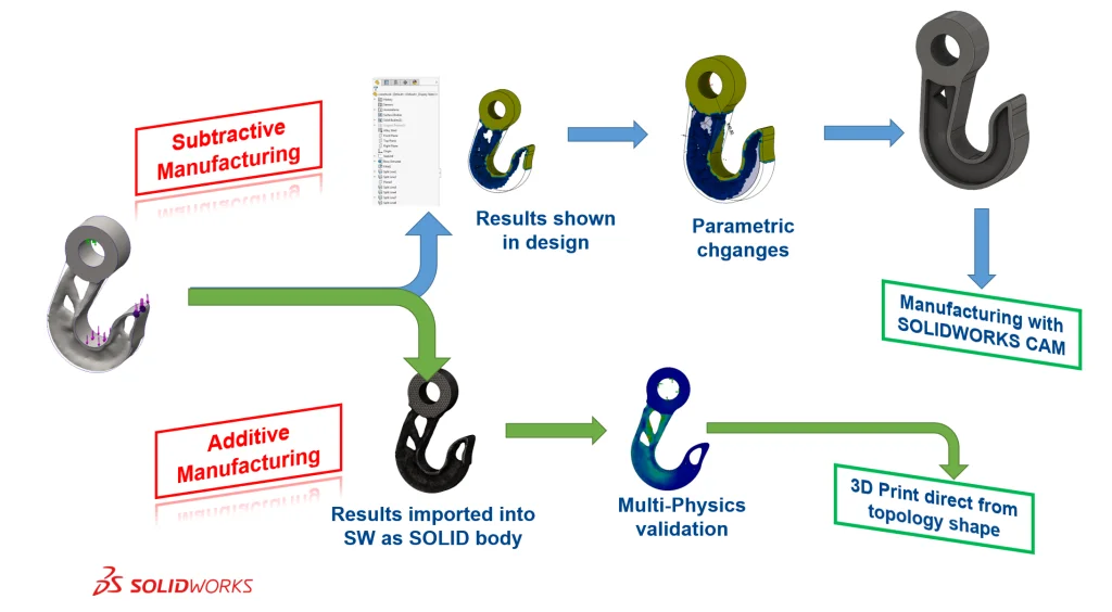
Using simulation tools in design isn’t just about validating an idea – it’s about powering innovation. With the release of SOLIDWORKS 2018, we’re empowering innovation with the new Topology Study. This new study type enables designers and engineers to develop innovative minimum mass components based on operational loads and conditions. Using a linear static solver, the topology study will ‘remove’ elements from the finite element mesh until the target mass or best stiffness-to-weight ratio shape is reached. This iterative process of element removal is limited by the study constraints such as maximum allowable deflection and any manufacturing controls.
But once you have this shape what do you do with it? This shape doesn’t just live in the simulation tool. It can be saved as a body (smoothed mesh) into your SOLIDWORKS part file. Once it’s in your design tool it is a full citizen of the design process, it can be managed in PDM, be the basis of further design changes with new versioning and be used in further simulation calculations. Additive manufacturing tools can be used to directly print components, incorporating a topology smoothed mesh body.
For applications that require traditional manufacturing, the results from a topology study can be viewed in the design environment like any other simulation result, to be used to guide any parametric changes such as cutouts and pockets.
Structural analysis is not a one shot wonder process; it is iterative, startling with simple models and loads progressing to complex geometry loads and even multi-physics studies. To aid this evolution of simulation needs for the designer and analyst, SOLIDWORKS Simulation studies can now inherit simulation set up from sub parts and assemblies into a full assembly. Loads can also be transferred from a motion, flow or plastics analysis.
Products that move, are shaken when being moved, or experience loads that vary with time can suffer from failures due to vibration and fatigue, when the operational forces are well below the ultimate failure load. Understanding the effect of vibrations, from operation or transportation, on your products is a complex and challenging task that SOLIDWORKS Simulation has streamlined with an intuitive UI coupled with powerful functionality. Engineers can now evaluate the vibration-driven stresses, displacements and component accelerations to assess the impact of any geometry changes to ensure product performance and durability under complex loads.
SOLIDWORKS Flow Simulation is another example of a type of analysis tool that was once the exclusive domain of the expert but is now used by designer and analyst alike. For the designer the easy-to-use analysis setup wizard has made previously challenging internal, external and thermal flow analysis accessible to all. And for the analyst the breadth and depth of physics and functionality enables complex problems such as non-Newtonian flows, rotating bodies, and electronics cooling. Flow Simulation has added to these advanced features in the 2018 release with the new free surface capability, which enables two immiscible fluids such as a liquid and a gas in the same volume. What does this mean? Well, we can solve three new types of flow phenomenon.
- Sloshing; a partially filled container experiencing movement
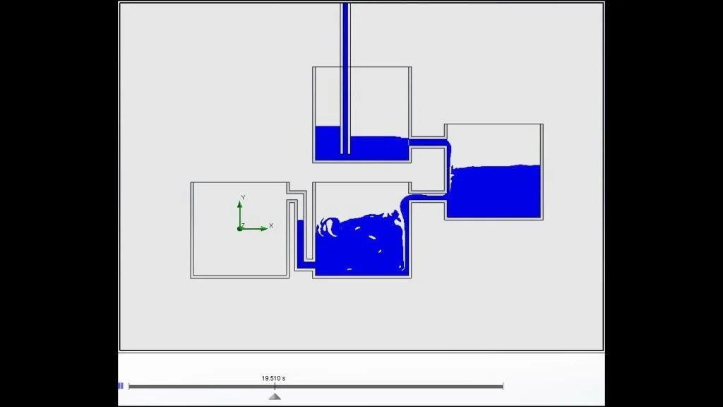
- Filling / Evacuation; tank emptying or filling times
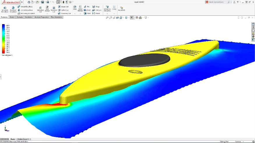
- Jet / Open Water; channel flow or flows from a nozzle where the flow is connected and continual (not a spray)
In its simplest application, a user sets the initial water level and then lets the physics take its course, either with a fluid motion, as in this simple boat on the water, below, showing both a bow wave and wake.
Or with the application of gravity, you can carry out tank emptying or filling processes.
The movement of a container (for sloshing) is created by a time varying gravity vector.
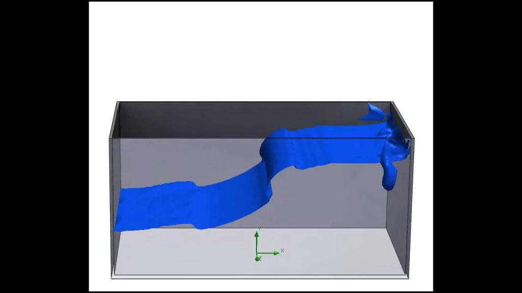
SOLIDWORKS Flow Simulation 2018 enables designers and analysts to tackle a whole new class of problems.
SOLIDWORKS Simulation and Flow Simulation enable designers and engineers to determine the performance of their products under operational loads. SOLIDWORKS Plastics is different; it assesses your designs in terms of their manufacturability by the plastic injection process. With SOLIDWORKS Plastics you can simulate both the part being molded and the mold used to create the parts to determine if you can mold your components as desired and find out if your mold tool will perform as expected. In SOLIDWORKS Plastics you are simulating the manufacturing process, looking for air pockets, weld lines, and time to fill to understand the impact of design on the part quality and mold cycle time.
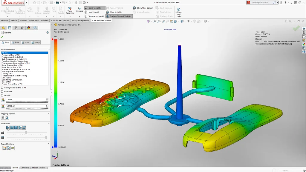
For Plastics analysis it is important to have accurate mold geometry, including runners, sprues, and cooling lines together with your component geometry in order to understand the complete manufacturing process. Analysis of the component is important to designers as they want to ensure that the gate locations not only ensure the correct fill but also to that all weld lines or sink marks are not visible to the end user. The engineer or analyst will want to take the plastic analysis one step further, to determine the structure and shape of the parts once they exit the mold too. SOLIDWORKS Plastics can determine the variation of plastics density and deformed shape, caused by uneven cooling of the part. This deformed shape can be imported back into SOLIDWORKS to compare the before and after versions of the geometry, which will let the design team know if the warpage is acceptable or if modification of the part, cooling lines or mold is necessary–all before the expense and time of cutting metal.
As I stated at the beginning of this blog, the goal of SOLIDWORKS is to enable all our customers take advantage of simulation from designers refining designs with the new topology or checking plastic part manufacturability to analysis looking for a deep understanding of the product performance with nonlinear analysis, dynamics and free surface flow. The SOLIDWORKS Simulation suite of tools delivers this with the 2018 release. Click here to visit the SOLIDWORKS designer to analyst page and see these tools in action.