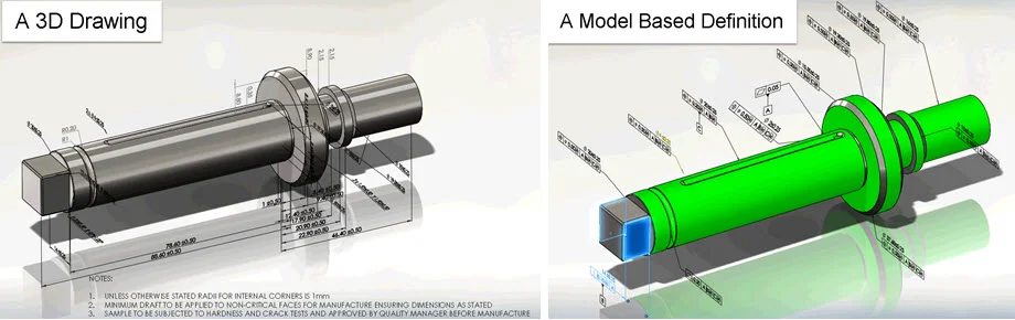

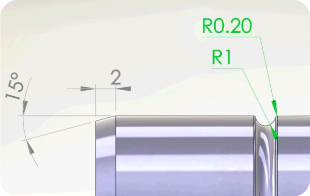
A year ago, I wrote an article about How to Dimension Silhouette Edges Using SOLIDWORKS MBD. This technique is often used to specify revolved bodies such as toruses in relief grooves, cones in chamfers, or shoulder heights on shafts and holes. Figure 1 below shows several examples in a detailed view of a shaft.
That post led to an interesting discussion about what is a 3D drawing and what is a model-based definition (MBD). So in this post, I thought it would help to clarify. In my opinion, to serve various use cases, MBD implementations entail multiple stages. 3D drawing is a beginning stage to meet 3D visual consumption needs, but far from the full potential of MBD.
A 3D drawing follows the 2D drawing habits. It simply converts 2D annotations onto a 3D model as shown in Figure 1 (above). Because of the inherited 2D conventions, 3D drawings may be easier to adopt initially. They typically define geometries such as edges, curves and vertexes in full details rather than defining features such as faces, holes, slots and pockets. The geometry definitions limit the potential of downstream manufacturing automations due to the lack of features.
Therefore, to serve the manufacturing process better, feature-based definitions are recommended because on the shop floors, what eventually get machined or inspected are faces, holes, slots or pockets. Edges, curves and vertexes are only the results of the features. No machinists would care about the distances between two points or curves. What they care about is the diameter of a cylinder or the distance between two faces.
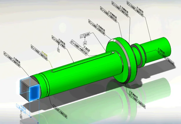
Furthermore, digital 3D models empower MBD implementations in unique ways beyond the drawing mentalities. For example, annotating features enables the cohesive applications of GD&T and the cross highlighting from annotations to features. Figure 2 shows the tolerance status of several faces in green to indicate they are fully toleranced. Also a width as the datum feature B is highlighted in blue once the annotation is selected. These intelligent 3D annotations can not only be visually read, but also be programmatically analyzed and acted upon by downstream manufacturing software applications, such as computer-aided manufacturing (CAM) and coordinate measuring machine (CMM). Automation is the major benefit of MBD.
To conclude, let’s come back to the various needs in MBD implementations. If your main goal is to convey the visual information in 3D intuitively, then 3D drawings can be a good start. If you want to lay the foundation for downstream manufacturing automations, then feature-based semantic definitions are recommended.
As a software developer, SOLIDWORKS provides both options to serve a wide range of needs. For example, Reference Dimensions work similarly to 2D detailing tools, so may help you with 3D drawing projects. On the other hand, DimXpert closely follows the ASME Y14.5 GD&T standard and ASME Y14.41 digital product definition standard, so can support you better from product specifications to manufacturing automations.
To learn more about SOLIDWORKS MBD, please watch the 22-minute webcast below and visit its product page. Also welcome to discuss with me at Twitter (@OboeWu) or LinkedIn (OboeWu).