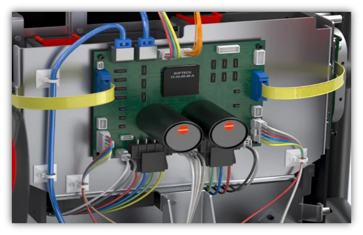

Every engineer knows the pitfalls that await when the electrical and mechanical sides of your design fail to integrate their workflows and data. A breakdown in communication leads to rising costs when it comes time for fabrication, with costly prototypes and those dreaded design changes. Missed budgets and deadlines impair your product development cycle in what could have otherwise been a successful release with the right tools for ECAD and MCAD integration and workflow productivity.
Costly Alternatives
Here are a few solutions that you might have already tried:
- Importing and exporting STEP models between your MCAD and ECAD software. This leads to a loss of potentially critical design data during each translation and a lack of real-time notifications of changes in either design environment.
- Creating time-consuming paper dolls or 3D-printed enclosures that pull your high-value engineers away from their specialized tasks.
- Manufacturing expensive physical prototypes.
Overall, these alternatives are both costly, time-consuming, and inefficient. If you could solve all of your design workflow and integration issues within the software where you first began your designs then you leave prototyping for what it’s best used for – testing your final product.
What kind of alternatives are available to tackle this growing problem?
What if you could…
- See changes made to your MCAD/ECAD designs within either environment and easily accept changes as they happen with linked design data?
- Run only one physical prototype, knowing that your design teams were successfully collaborating throughout their entire development cycle with an integrated workflow?
- Use native mechanical and electrical models in your ECAD/MCAD environments without having to constantly import and export files?
Workflow Collaboration is the Key
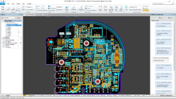
SOLIDWORKS PCB takes all of the guesswork out of your workflow collaboration between your MCAD and ECAD designs. Combining the best technology in PCB design with direct integration with SOLIDWORKS through native file format support provides you with data translations that are both accurate, managed, and fully in-sync across the entire spectrum of your design.
Easily link your mechanical models of components in SOLIDWORKS with the electrical libraries for components in SOLIDWORKS PCB, keeping the data between the two linked and updated whenever changes are made.
Actively make changes to component placement, board shape, and mounting holes on your PCB directly in your SOLIDWORKS environment, syncing data with SOLIDWORKS PCB easily with managed ECOs.
Ensure that your design data is as accurate as possible by using SOLIDWORKS native file format directly in SOLIDWORKS PCB. By using native lossless files instead of error-prone translations, SOLIDWORKS provides the most accurate representation of your design intent and keeps your mechanical and electrical data in sync.
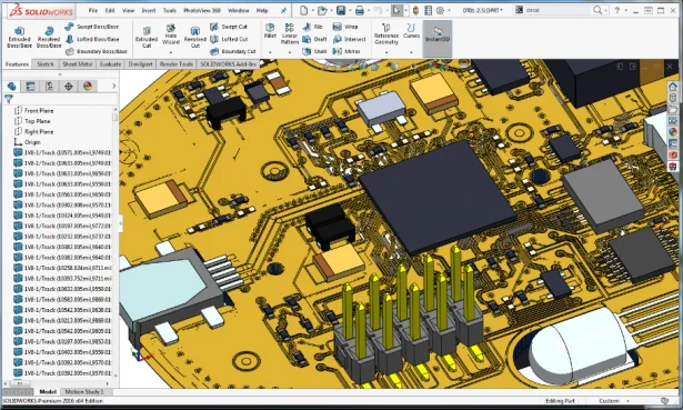
Gain an even greater degree of control over your PCB design process with access to copper traces from your board designs. Native board data provides a new level of analysis capabilities directly within SOLIDWORKS with thermal, vibration and other simulations.
ECAD/MCAD Integration Ensures Success
Breakdowns in communication between your MCAD and ECAD designers are a thing of the past. SOLIDWORKS PCB achieves the first-ever ECAD/MCAD integration that brings together both sides of your design process in a unified data structure and managed ECO process. SOLIDWORKS PCB is the first and only ECAD software to support SOLIDWORKS native file format, leaving you with the confidence you need to know that your design data is accurate and integrated.
Learn more about how you can bridge the gap between your MCAD and ECAD design teams with SOLIDWORKS PCB 2017.