
Conceptual Designer is a useful 3D Modeling app on the 3DEXPERIENCE platform that allows users to create and animate 3D parts. Over the past few months, I have been creating various mechanisms of multiple levels of difficulty with it and creating the animations of the mechanisms in motion. My first blog discussed how I used Conceptual Designer to create and animate the motion of Chebyshev’s Plantigrade Machine. You can read that blog in its entirety here.
Animating the Motion of a Four-Piston Engine with SOLIDWORKS Conceptual Designer
In this blog we will discuss the mechanisms that I created and explain the steps I took to make them.The radial engine has been used for over a hundred years, mainly in aircraft. It was the primary type of engine used in World War I aircraft on the allied side. It was also used in many American armored vehicles in World War II. It is still used in some Russian aircraft and other homebuilt aircraft. It is a very interesting engine to create, connecting all eight cylinders to the one crank.
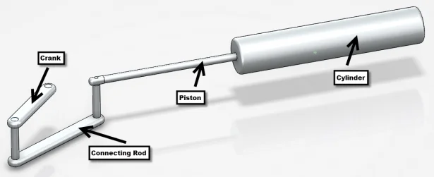
I started making the engine with one of the cylinders. I made it with no particular scale or proportion in mind so it is probably not an accurate representation of the proper scale of a radial engine. The cylinder has a 1” inner diameter and an interior length of 6”. The hole in the center for the piston to go through is ¼” in diameter.
The piston was the next component I made. The piston head has the 1” diameter and ¼” thickness. The end of the piston is a ¼” thick and has a ⅛” diameter hole for the link pin to join the piston to the connecting rod. I made the crank next, giving it a length of 2.5”. I put a pin in one of the holes, aligned it with the piston, and fixed it in place; this gave the proper alignment and I used the distance between the empty end of the crank and the end of the piston for the length of the connecting rod. I added a couple of pins to join the connecting rod to the crank and piston. Using Conceptual Designer’s instant motion feature, I clicked on the crank and it made the entire cylinder move like a normal piston and cylinder.
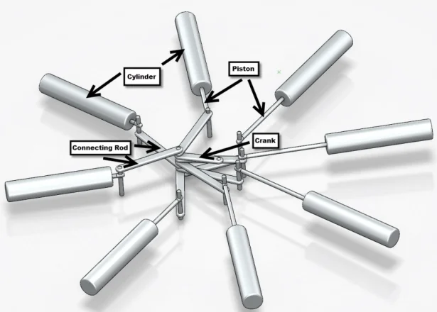
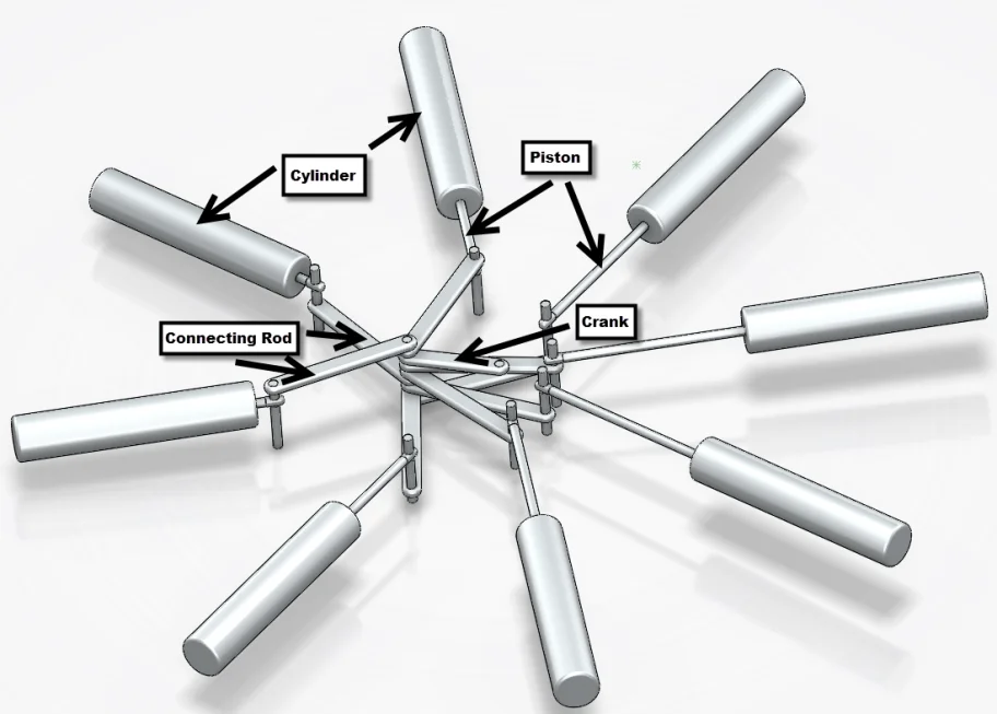
Now that I had one cylinder made, I had to think about how to make eight of them run in conjunction. I started off by making a four-cylinder version, offsetting the connecting rods from their respective pistons to make sure no links overlapped. The alignment was accomplished by using the parallel and perpendicular mates to keep the pistons and connecting rods in line. Once again, I used the instant motion feature to simulate the proper motion. The real trick came when I decided to make an eight-cylinder version. This required me to put angle mates between the crank and the new piston. Once each cylinder was in place, I fixed it in place so that I could move the rest of the mechanism without disrupting the alignment I had just created. I repeated this for each cylinder, and eventually arrived at the final version with eight cylinders. Using the same motion study that I created for the four-cylinder version, I got the engine running.
To learn more about SOLIDWORKS Conceptual Designer, check out the resources available on the SOLIDWORKS product page here.