
A 5.8 magnitude earthquake shook the East Coast of the United States on Tuesday. While the resulting structural damage has not been extensive, there is always the danger of loss of life and extensive loss of property in such natural events. Nowadays, software packages are extensively used to examine different variations of designs so that for a given loading, the design is both safe and cost-effective.
Let’s take the Washington Monument as an example. Some minor damage has been observed in terms of localized cracks, but bigger problems could have occurred. The effect of the quake on the soil could have resulted in minor tilting of the monument. An extreme case of such a tilted structure is the iconic leaning tower of Pisa in Italy.
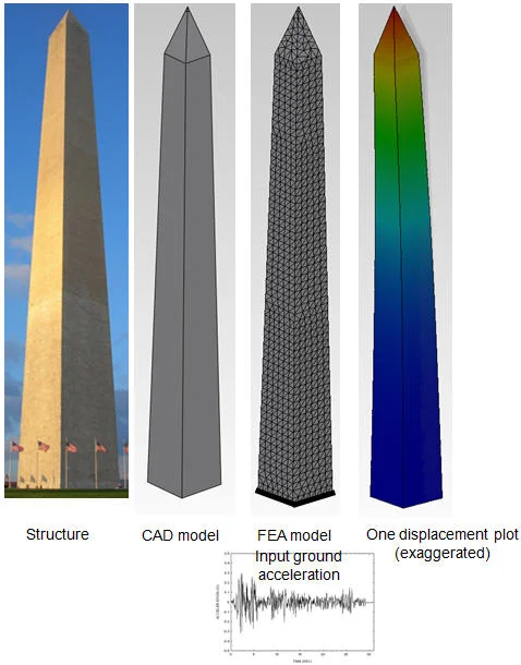
Another subject of interest could be the examination of the movement of the top of the monument. As the ground shook at 1:51 pm EST, the visitors on the observation level at the top of the monument must have experienced excessive back-and-forth motions, not the best place to be at the time! While the masonry structure of the Washington Monument makes the behavior more complicated than a modern concrete or frame steel structure, the structure itself is (essentially) a simple cantilever.
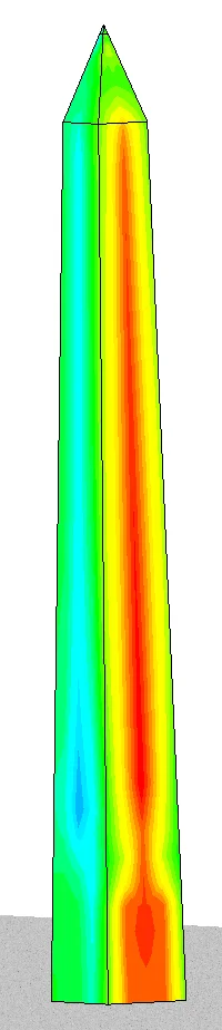
The way SolidWorks Simulation would handle such a problem would be as follows: Starting with a 3D CAD geometry and using the well-established Finite Element Method (FEA), the model would be discretized into a set of elements. Appropriate material properties would be defined, the ground would be approximated with a support condition, and a uniform base excitation would be applied using the data collected from devices such as accelerometers representing the earthquake, or in the form of other input data depending on the type of analysis conducted. Running the numerical analysis, a lot of data will be calculated throughout the model, among them the amount of displacements experienced by an observer at the top.

While in this case, simulation is used after the event has actually happened, for forensic purposes, retrofitting or just to get a better understanding of the event or structural behavior, the real power of simulation comes at the design level, before anything is ever built. By numerically examining many different alternative scenarios, this type of virtual prototyping is going to result in more efficient designs, with a higher reliability, faster time to market and at a lower cost. SolidWorks’ Simulation products enable the engineer to do just that. The particular analysis explained above falls within the linear dynamic module.
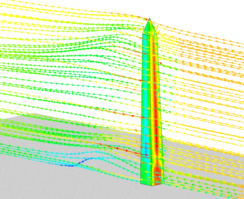
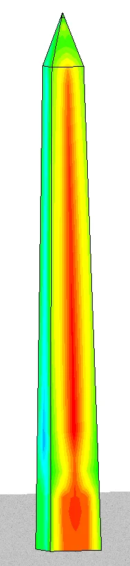
These days, the other piece of news is about Hurricane Irene which may possibly reach the Washington DC metropolitan area shortly. Using SolidWorks Flow Simulation, a Computational Fluid Dynamics (CFD) package, one can model the wind blowing and further study the resulting pressure distribution on the monument. In conjunction with the stress analysis module, one can automatically export the calculated forces from the CFD package and into the FEA stress analysis package and calculate the displacement at the top of the monument as well as the resulting stresses throughout the structure.
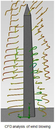
The force due to wind scales as a square of wind velocity, or V^2. The National Hurricane Center predicts 40-50 knot (46-57.5 mph) winds in the vicinity of the Washington Monument, so the 10 knot change in wind speed means an increase in force by about 56%.
Editor’s note: This entry is published on behalf of the SolidWorks Simulation team, who are responsible for both the text, images and analysis. Good work guys!