Preventing mechanical fatigue with SOLIDWORKS Simulation
The de Havilland DH 106 Comet was the world’s first production commercial jetliner, commencing its maiden flight on 27 July, 1949. The design featured turbojet engines built in to the wings, square windows and a pressurised cabin.
The Comet made an immediate impression with the British Monarchy, with notable passengers including The Queen Mother, Queen Elizabeth and Princess Margaret. Flight time aboard the Comet was significantly shorter than all other prop-driven aircraft of that era, and in their first year Comets carried 30,000 passengers.
Despite the incredible early success of the aircraft, the structural integrity of the Comet soon came into question after a number of high-profile incidents resulting from fatigue in the fuselage of the plane.
The repeated pressurisation of the cabin caused the corners of the plane’s square windows to form cracks and, following the deadly accidents, designers soon realised the importance of analysing mechanical fatigue – an element of design that SOLIDWORKS Simulation incorporates flawlessly.
Finite element analysis
Finite element analysis is one most established computational process of determining how a product will react to outside influences in the real-world, as opposed to in prototype simulation. Such studies can also be set up to incorporate multiple variables such as heat, vibration, pressure and contact between components, factors which would be near impossible to easily and feasibly study within a real-world setting.
Creating a Finite Element Analysis is tricky – check out the #TechBlog to learn some tips! https://t.co/TIX7x5KuNq pic.twitter.com/sZsU3jQzXL
— SOLIDWORKS (@SOLIDWORKS) June 17, 2016
//
While using simulation techniques can reduce the cost of developing a product, it is vitally important that the mechanical integrity of the design be put first. SOLIDWORKS Simulation provides a reliable method of identifying and resolving these issues, and is crucial in solving fatigue problems before they can arise.
Determining structural and mechanical fatigue
When identifying the potential for mechanical fatigue, a constant and ultimate load is decided, and safety measures put in place to prevent the structure from experiencing this load. Across the general use lifecycle of a product, however, it’s unlikely that it will be experiencing the maximum level of stress at all times.
To address this, simulation software is used to determine how the product or structure will react when subjected to multiple variations of a load or stress over a determinable length of time. Had such knowledge of fatigue been sufficiently mature during the time of the Comet’s use, testing for fatigue would have alerted designers to the structural weaknesses that the windows would exhibit under pressure.
Determining fatigue requires a varied load allowance to be repeated at a level that doesn’t exceed the ultimate load decided upon. The level of fatigue that a product or design will suffer is determined in three stages:
- Initiation – Predictions are made on the amount of stress to specific concentrated areas
- Propagation – The driving force of fatigue and the material’s ability to resist fracture is calculated
- Final fracture – The fatigue and driving force of the structure reaches the point that a single load would cause the structure to fracture
While the final two stages of this process are just as important to the overall design structure, the initiation stage of mechanical fatigue determination is the most crucial.
 SOLIDWORKS Simulation software can help identify mechanical fatigue in a design.
Reducing the risk of cumulative damage
Embryonic cracks – those measuring between one and 10 microns in height – have been studied in natural polymeric materials such as rubber, and organic polymers including polypropylene, thermoplastic polyurethane and polyvinyl chloride.
These cracks are invisible to the human eye, but were detected using a technique developed – belatedly, in the context of the Comet – in the mid 1970’s known as small-angle x-ray scattering where the behaviour of these submicrocracks in polymers were studied using light scattering.
Thankfully, as times have advanced, we have products like SOLIDWORKS Simulation that can speedily and efficiently adjust designs, determine projected life cycle and integrate maintenance or part replacement procedures.
Today’s Simulation Step-Up video covers model isolation and boundary conditions #TechBlog https://t.co/xs1K7n9LRV pic.twitter.com/9VqWQ4LxfK
— SOLIDWORKS (@SOLIDWORKS) June 17, 2016
Calculating the fatigue of a product
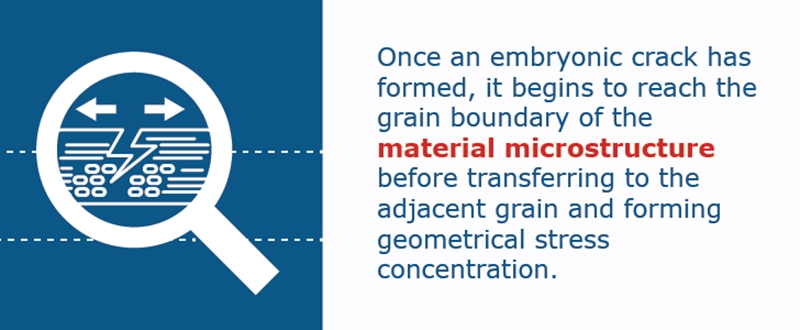
Once an embryonic crack has formed, it begins to reach the grain boundary of the material microstructure before transferring to the adjacent grain and forming geometrical stress concentration.
The aim, of course, is to create prototypes and designs that will always remain below the fatigue limit threshold and provide an infinite lifecycle. However, for products that require a fixed lifespan, and in many cases, restricted by other seemingly conflicting parameters such as ensuring the largest useable space while minimising the mass (weight) of the object, designers are able to plan and create disposable items with an accurate shelf-life.
Real world applications
Let’s take a look at how SOLIDWORKS Simulation would work in relation to testing a train for mechanical fatigue. At a particular point in the journey, the software will incorporate various strains and stresses presented to the carriage.
We want to address and simulate the following; environmental effects such as wind, rain or snow, the weight of passengers and the angle of lean and pressure on the structure of the train, and the general wear that would accompany a train running along the metal tracks.
Normally, these processes would have to be addressed simultaneously, with the total sum force of the action being taken into account at a specific point. However, with simulation and visualisation software, you’re not only able to separate each of these outside forces, but collect the data in summary and simulate these stresses and events at any point in the lifecycle of the product.
By looking at the combination of these processes, you’re able to determine what the structural and mechanical limits of the train would be, and decide when appropriate maintenance or replacement parts will need to be implemented into the design.
 Determining the fatigue limit of a design can help identify the cause of fracturing.
Why choose SOLIDWORKS?
By understanding the ways that materials within a design can experience stress at grain boundaries, and the subsequent dislocation and damage nucleation, we can begin to improve the ductility of materials, and therefore the overall product life.
Developing new methods of strengthening and reinforcing designs requires the understanding of these processes. SOLIDWORKS Simulation works effectively to incorporate loading and stress scenarios for designs and can save vast amounts of time and resources over traditional prototype testing
When testing the mechanical fatigue of a structure, simulation software provides an intuitive, intelligent design process. Contact us today if you’d like to learn more about SOLIDWORKS Simulation, or download one of our whitepapers to read more about what CAD can do for you.


