What do people mean when they talk about “CAD-embedded simulation?”
For the last few decades, we have seen more and more simulation tools integrated in CAD systems. This positive trend made simulation accessible to all product engineers. However, I believe it is important to understand what “CAD-embedded simulation” really means, as this term might have been over-used.
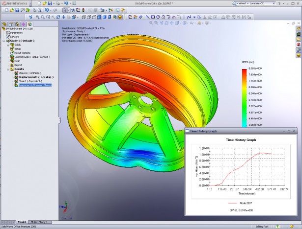
First of all, these simulation tools (FEA, CFD, Electromagnetics) share the same user interface as the CAD software. This is the bare minimum, but in my opinion, it is not enough to consider them CAD-embedded. There should not be CAD model translation between CAD & simulation. The CAD model is in fact the future FEA model once meshed & restrained. The two systems, which should be considered as a single engineering solution, share similar commands and workflow to shorten the learning curve and make simulation set up as transparent as possible for the users.

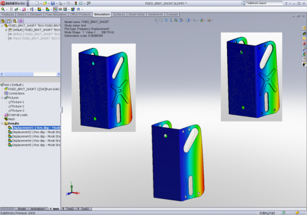
Next, CAD integration means strong support of the CAD model. The integration offers the possibility to test any model the CAD system can open (wide range of formats). The design tools are often used to prepare the geometry, for instance by removing chamfers, fillets and small geometrical details that are irrelevant for the simulation. Basically, the preparation of simulations conducted via CAD software is completed much faster than with standalone simulation software. When designing a product, engineers use design configurations or table family for product variations (different number of ribs, dimension changes, number of holes, etc.) which become simulation scenarios to compare the performance and quality of these variations. Engineers can then easily run “what if” scenarios and find the best solution according to their criteria.

CAD integration is nothing if a strong associativity is not maintained between CAD & simulation. Any design change on any topology (solid models, surfaces) is detected and updated in the simulation model without any loss of the simulation set up. Indeed, in CAD-embedded simulation tools, the boundary conditions are applied directly to geometry instead of the elements themselves. The elements associated with that geometry then inherit those boundary conditions ensuring tight associativity.
A strong value of real CAD embedded simulation lies in the fact that the CAD model parameters are leveraged for the simulation. For example:
- The materials defined while designing the product are used in the simulation for the material properties definition
- Dimensions such as the thickness of a sheet metal part become a simulation parameter for shell definition
- CAD fasteners such as pins and bolts can be translated into simulation connectors with their location and resistance properties
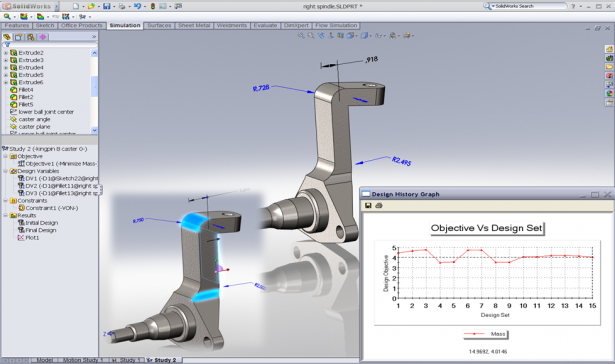
- The model dimensions are used for design optimization so the engineers can find the best dimensions (thickness of a part, diameter of a hole, mates between components…) for the best design.

- The topology of the geometry is recognized and used for the mesh type definition (sheet metal is recognized as a thin part and then meshed as a shell. A structural member is recognized as a beam)
- The mates (coincident, coaxial…) become kinematic joints automatically for a quicker definition of a rigid body motion simulation

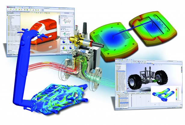
Finally, the engineering solution shares similar tools so that engineers don’t need to duplicate software and be more productive. For example, they would use the same communication tools to share 3D CAD & simulation models to piers in one shot. To automate CAD creation and simulation computation, engineers will use the same batch Run tool for a better efficiency.
This is not an exhaustive list of what real CAD embedded Simulation offers but this should, hopefully, draw you a clearer picture of what you would get with such a solution.
To conclude, conducting virtual simulations in 3D CAD software is faster and easier for product engineers. The result is that more simulations can be conducted in the same amount of time, providing more insight to these engineers. That, in turn, leads to better design decisions.
Want to learn more about SOLIDWORKS Simulation? Check out our First Look at Simulation video to see how simulation could improve your own designs and reduce prototypes.


