
Sometimes you come across a term in simulation that doesn’t make much sense and seems to have been put there to confuse and confound. One such term that I was asked about recently is the purpose of the Jacobian check, a mesh checking tool that I know hardly anyone uses but is one of those things that can be very useful.
The whole purpose of checking your mesh is to see if it is well defined. A highly deformed element becomes inaccurate and a mesh created with whole regions of badly defined elements will just serve to lead you astray. And where do elements tend to become deformed? In areas of highly curved geometry, which is often where you are interested in knowing the results.
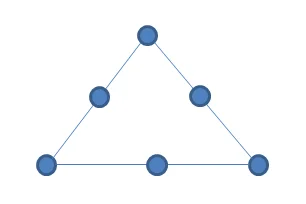
So what is the Jacobian check I hear you say? Well, consider a normal tetrahedral element with mid-sided nodes.
If those mid-sided nodes lie directly between the corner nodes, then the element is not deformed. However, the moment you begin to move the mid-sided nodes away from this line, to track the edge of a piece of geometry say, then the element begins to deform.
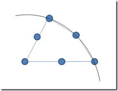
The Jacobian check is a measure of how deformed your element has become. A perfectly straight sided element has a Jacobian of 1.0 and is ideal, and the Jacobian ratio increases as the curvature of the edges increase.
The actual calculation is done based on a series of points inside the element called Gaussian points. The user can choose how many of these points to use in the Jacobian check when they create the mesh by selecting 4, 16, 29, or the node locations as the points at which to base the calculations on.

So performing a mesh quality check for the Jacobian generates a contour plot allowing you to identify areas where you may need to increase your mesh density, replacing a few badly deformed elements with a greater number of better shaped elements.
In the example below my test component has firstly been meshed with a course mesh and then a Jacobian check has been performed. The legend reports a Jacobian ratio of 1.0 as blue and shows how the main body of the straight edged geometry can be nicely modelled with straight edged elements. But the hole in the middle requires the element edges to become curved and so the Jacobian ratio increases, here to a value of 1.59.
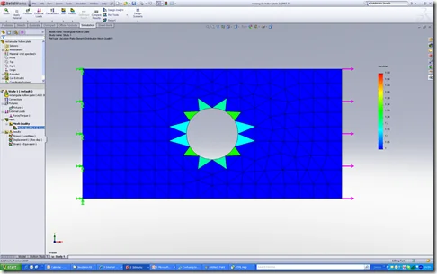
Simply remeshing with a fine mesh improves the maximum Jacobian ratio to 1.19 showing how more elements around the circle mean they are less mishapen.

It is generally accepted that a Jacobian ratio below about 40 is acceptable in most cases so you have to balance mesh density with run-times, perhaps refining the mesh with controls in certain areas rather than across the entire part. And as I’ve said before, always have a sanity check and ask yourself if the highest Jacobian ratio is in an area where you will see the highest stresses anyway.
Technorati Tags: Tips & Tricks,SolidWorks Simulation,Jacobian Ratio