The Tale of Two Captains: Captain Marvel
Well as many of you probably know, Captain Marvel hit theaters last month and it has been a gigantic hit. One of the people who joined the masses in the theater was our very own Marvel expert Mike Dady. After seeing just how powerful Captain Marvel was on the big screen, we asked Mike to find out exactly how powerful, with the help of SOLIDWORKS Simulation.
For some reason, I always enjoy that scene when I watch it. Today, Alignex will explore the powers of a lesser known captain in the Marvel Cinematic Universe, Captain Marvel.
SOLIDWORKS Simulation can easily determine the force Ms. Danvers used on Grandma Skrull in this scene, but we like to think big at Alignex. In a previous video, we determined how much of a beating Captain America, and his shield, can take. We found it’s quite a bit. Captain Marvel is a powerhouse in the comic books and things are clearly no different in the Marvel Cinematic Universe. So let’s use SOLIDWORKS Simulation to find out what those cosmic beams are doing to that railroad bridge.
Modeling and Simulation Setup

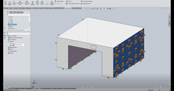
Modeling the bridge was the simplest part of the setup. It was pretty easy to create geometry that accurately represents the bridge. A split face was added for an approximation of the ‘cosmic beams’ impact area for loading the structure. Lastly Radii were added to the inside corners of the bridge to prevent any stress concentrations.
A Static Simulation was used to load the bridge. However, a Non-Linear Dynamic Simulation would be viable solution as well. To simplify things, plain Concrete was used for bridge Material. Because of concrete’s dual nature, we will take a look at the tensile and compressive stress in the results. To hold the Model in place, the outside faces of the bridge are fixed, and a roller/slider is used on the bottom faces.

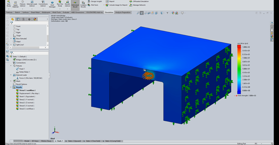
Initially, a force was applied normal to the bridge face. 100,000 lbs. was the starting load applied, and once the first simulation finished, it was obvious that load was far too low to fail the bridge. For fun, I created another simulation with the load tilted upward 5 degrees to examine how the change impacted the bridge.
A mesh control was added on the load face. This made the stress values more accurate and also blended the stresses more smoothly outside the load area. Once the loading was increased enough to fail the concrete at the load location, a mesh control was needed on the inside radii. The max stress on the model was located in the radii and that is not accurate.
Results

As mentioned, the 100,000 lb load was hardly enough to scratch the surface of the bridge. The load had to be increased drastically.
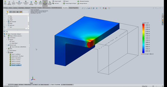
A 2 Million pound load was needed to get the Top of the bridge to exceed the minimum tensile strength of concrete. However, the bridge won’t ‘break’ until the force is large enough to crack the front of the bridge as well.
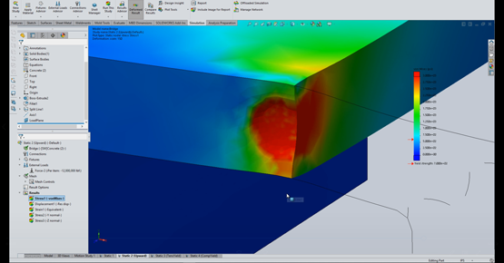
When we apply a 12 million pound load, the compressive stresses reach concretes minimum compressive strength. We can also see the deformed wave of the load and how the Tensile Stress on top is now 4 times the minimum tensile strength. I think the bridge lost this battle.

When we add the upward vector, the same 12 million pound load still shows a strong compressive stress on the face of the bridge. As expected, the stress distribution favors the top of the bridge. Further examination shows the force is definitely giving the bridge an uppercut based on the deformation.
Captain Marvel is definitely a powerhouse, exerting millions of pounds of force with those beams. Imagine having power like that at your fingertips with every project. Well with SOLIDWORKS Simulation, you can.


