
SOLIDWORKS Inspection 2018 enables users to leverage their existing 2D and 3D CAD files to streamline their quality control and documentation processes even more. Additionally, the support of SOLIDWORKS parts and assemblies also enables companies to expand their drawing-less manufacturing strategy all the way to the quality department.
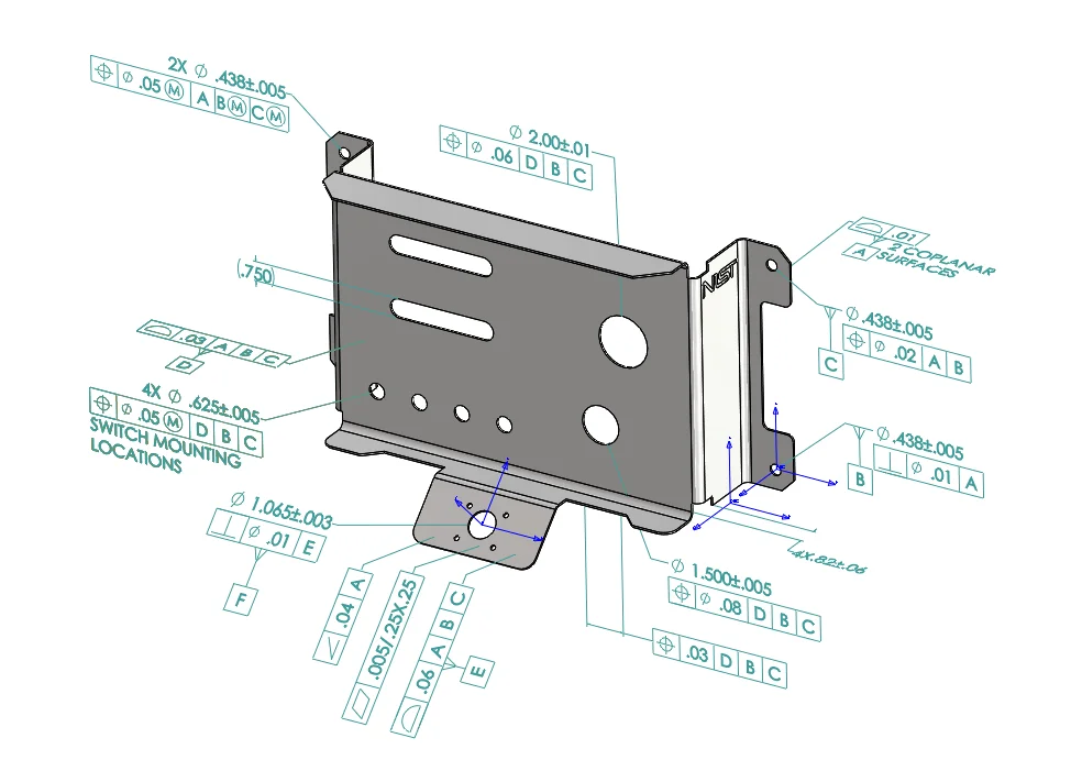
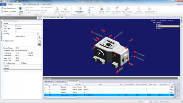
If your SOLIDWORKS parts or assemblies contain 3D annotations or Product and Manufacturing Information (PMIs), then you can create a new inspection project and extract all the information needed for your inspection checklist.
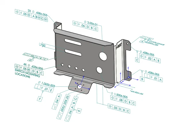
The process is similar to working with 2D drawings (*.slddrw). In just a couple of steps, you can set up a project and then define with simple checkboxes if you need to include or exclude Dimensions, Notes, GD&Ts, Hole Callouts, etc. SOLIDWORKS Inspection automatically adds the balloons to the PMIs so that quality inspectors can refer to the inspection spreadsheet and the 3D model to understand the characteristics to inspect.
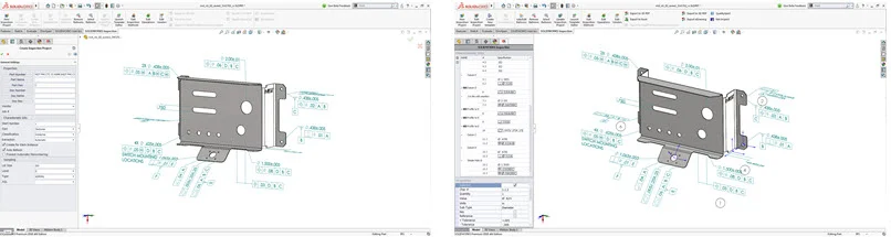
In addition to the Automatic extraction mode, a Manual mode is also available.
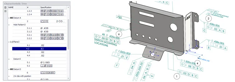
Similar to working with a SOLIDWORKS drawing, the characteristics are listed in the Characteristic Tree and you can modify each characteristic’s properties to include additional information, such as the Operation, Classification, Method of inspection, or just re-order them.
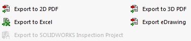
Once the inspection project is completed, you can generate a Microsoft® Excel report, a 2D PDF, a 3D PDF (if SOLIDWORKS MBD is available) or an eDrawing file.
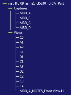
Using the SOLIDWORKS Inspection Standalone you can also open and import 3D files from other CAD vendors directly into your inspection project. The following formats are supported with the 2018 release of SOLIDWORKS Inspection: · 3D XML files · PTC® and Creo Parametric files · CATIA® V5 CATPart and CATProduct files · CATIA® V5 CATDrawing files · AutoCAD® DWG files
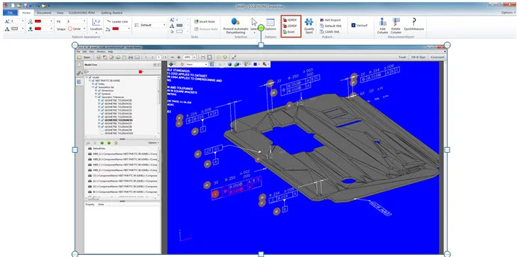
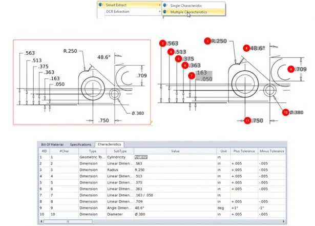
Once the files are imported in the project, the 3D Product and Manufacturing Information (PMIs) can be simply extracted using the new Smart Extract feature that directly reads the 2D or 3D CAD file information based on pre-defined settings similar to those found in the SOLIDWORKS Inspection Add-in.
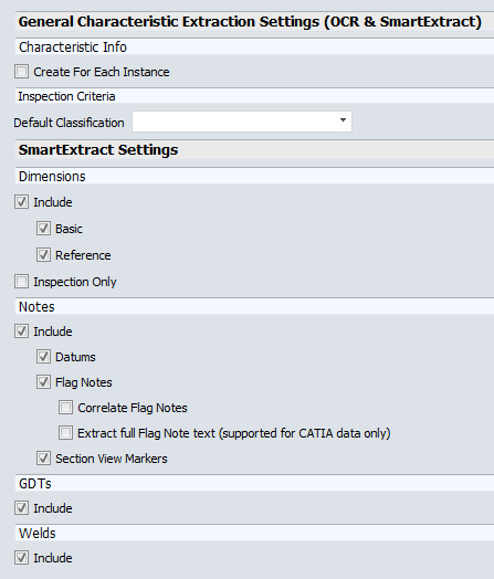
Once the extraction settings are specified, you can then click on individual characteristics to add them to your report or can box select multiple characteristics.
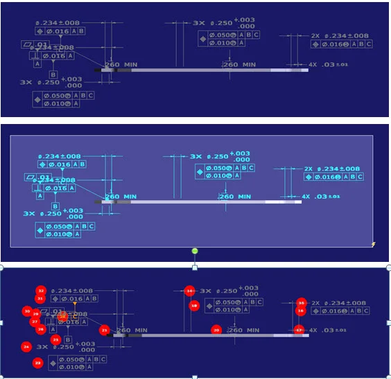
Navigating between the different views of the 2D or 3D file is made possible using the navigation tree in the top right corner.
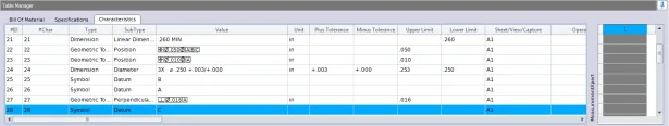
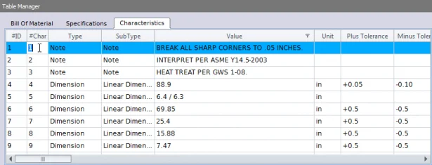
Also, similar to working with PDF or TIFF files, the characteristics are ballooned and added to the Bill of Characteristics.
Once your inspection project is completed, you can generate a Microsoft® Excel file, a 2D PDF or a 3D PDF.
The support of 2D and 3D CAD files drastically simplifies the creation of all your quality documentation and really eliminates the need to extract information from image type documents like PDF or TIFF files, which could be significantly more time-consuming.
New AutoBallooning Tool
SOLIDWORKS Inspection 2018 has dozens of new time-saving features. The new Smart Extract tool is one of them and allows users create their inspection sheets faster by extracting multiple characteristics at once instead of one at a time using the Optical Character Recognition (OCR) feature.
If the PDF document has a searchable text layer and supports Smart Extract, users can extract multiple characteristics at once using pre-defined settings. The quality of the extraction depends on the software that was used to create the 2D drawing.
New Customizable Balloon Numbering Features
When creating inspection sheets, there are multiples cases in which you might want to have a customized numbering of the characteristics. For example, you might want to have all the characteristics that need to be verified after a specific operation numbered 101, 102, 103, etc… and the ones that need to be expect when the part is finished 201, 202, 203 etc…
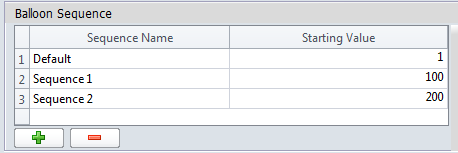
In order to achieve this, balloon sequences can now be created in the options and assigned to the project’s characteristics. New sequences can be added or removed and Sequence Name and Starting Value can be customized.
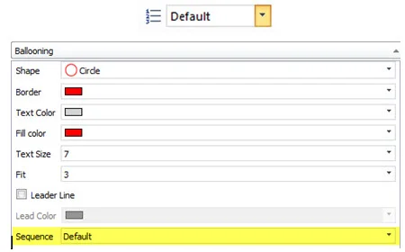
Characteristics ballooned by the user will be numbered based on the sequence selected in the Command Manager or in the characteristic window.
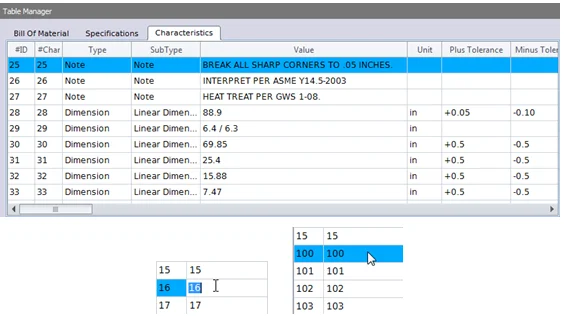
If the user select “Sequence 1,” all new characteristics added will be numbered 100, 101, 102, … If a particular sequence already has characteristics, any new characteristic will be added to the end of the list (103 in this case). If sequences are modified, the balloon numbers will also update accordingly.
Additionally, you can also directly renumber characteristics in the Bill of Characteristic to introduce gaps by double clicking on the Characteristic Number field. All characteristics below it will be renumbered accordingly.
Using the new Balloon Sequence or Customizable Balloon Numbering users can precisely balloon their documents without restrictions. With more flexibility, they can create exactly the report they are looking for. Keep in mind, however, that Balloon sequencing, balloon increment and customizable balloon numbering can only be used independantly of one another in a project.