Place Datum Feature Symbols to Your Preference Using SOLIDWORKS MBD
There are several frequently asked questions about the datum feature symbol placement in SOLIDWORKS Model-Based Definition (MBD), so let’s explore together in this article.
There are four major types of placements. The symbol can be applied to a feature surface, a leader line, a dimension witness line or a geometric dimensioning and tolerancing (GD&T) feature control frame. Different companies often have different preferences so SOLIDWORKS MBD supports all of them as shown in Figures 1, 2, 3 and 4.
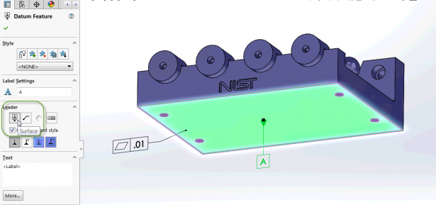
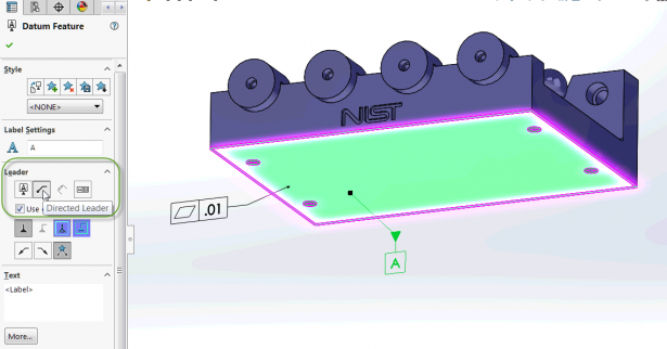
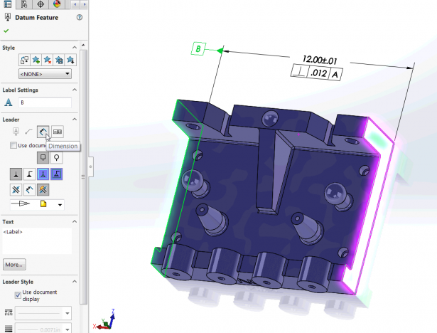
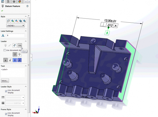
You may have noticed that in Figures 1 and 2, the dimension witness line attachment style was disabled. That was because the datum feature A defined a surface, not a feature of size. The symbol didn’t have a dimension to attach to. The dimension attachment option was enabled in Figure 3 because the datum feature B defined a width size feature. This feature has a size dimension and the datum symbol can be attached to the witness line.
A key point to highlight in Figure 3 is that SOLIDWORKS MBD automatically aligned the datum symbol B leader line with the width size dimension line and arrow heads. You can adjust the leader length of B, but cannot move B up or down on the witness line. This is not by accident or for aesthetic purpose. It’s required by the ASME Y14.5 standard. In order to specify a width feature, the datum feature symbol must be aligned with the dimension line arrow heads. Here is an excerpt from the standard, “(The symbol shall be) placed on the dimension line or an extension of the dimension line of a feature of size when the datum is an axis or center plane. If there is insufficient space for the two arrows, one of them may be replaced by the datum feature triangle.”
On the other hand, in the case of Figure 3, if the datum feature symbol B was not aligned with the dimension line, then it would have defined a planar datum feature, rather than a width feature. Figure 5 shows an example.
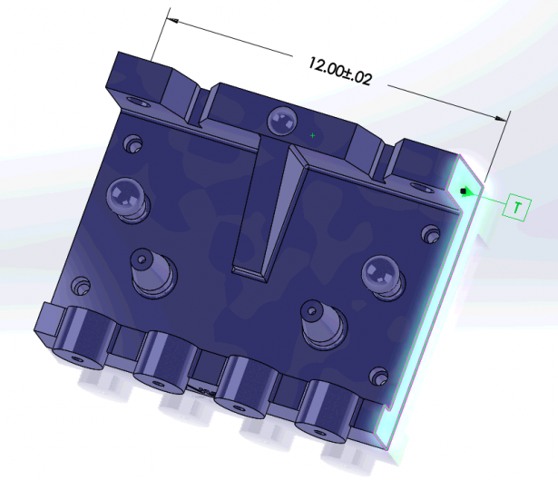
Besides a width, there are other applicable size features, such as spheres or holes. Figure 6 provides an example of attaching a datum feature symbol to a sphere diameter dimension.
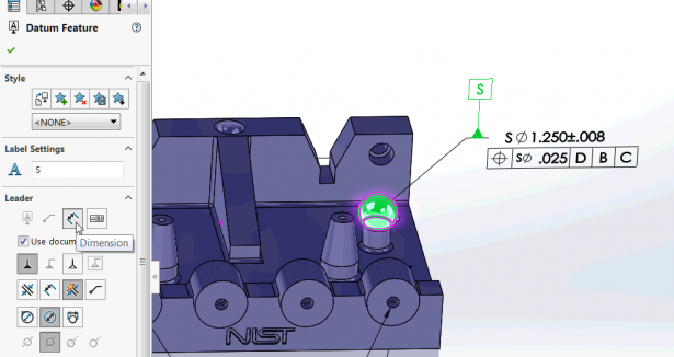
Lastly, you can also adjust the datum symbol styles on the property manager as shown in Figure 7. Their results are instantly visual, so I’ll leave them for you to try out and have fun.

To learn more about how SOLIDWORKS MBD can help you with your MBD implementations, please watch this video below and visit its product page. Also welcome to discuss with me at Twitter (@OboeWu) or LinkedIn (OboeWu).


